Getting Started Tutorial 5 : Mechanism and Scene Configurations
In this tutorial, you will learn how to use the Configuration feature in Vortex® Studio Editor. Configurations allow you to create multiple variations of a mechanism or scene within a single file. They provide a convenient way to develop and manage variants with different components, equipment, or other parameters.
For this tutorial, we will be using the forklift mechanism and scene from the Vortex Demo Scenes. The default location is C:\CM Labs\Vortex Studio Content <version>\Demo Scenes\Equipment\Forklift\ where <version> is the currently installed version. Note that both already have a few saved configurations – feel free to experiment and see how they interact with the ones you create yourself.
For more details, see Configuration.
Prerequisites
You need to have Vortex® Studio and the Vortex Studio Demo Scenes installed to be able to follow all steps in this tutorial.
Setting Up Work Copies of the Mechanism and Scene
In this section, we will open an existing mechanism and scene, and save a copy to experiment on.
- Open the Forklift scene, found in your Vortex Demo Scenes folder: (
../Scenario/Forklift Scene/Forklift.vxscene). - Create a Workshop Examples folder where you will save your work. Use Save As to save a working copy of the scene in the new folder.
- In the Explorer panel of the scene, locate the forklift mechanism. Open the forklift mechanism by double-clicking it.
- Go to the Home page and click Options. Make sure Keep default lights ON when adding new lights is checked.
- Right-click in the 3D View and deselect Debug Display > Geometry.
- Use Save As to save a working copy of the mechanism in your Workshop Example folder. Do not check the Save as Copy box in the resulting dialog.
Inserting a New Mechanical Configuration
In this section, we will add a configuration to an existing mechanism.
- Go to the tab with the forklift mechanism. We will now create a configuration to allow us to select whether the rotating warning light is present on the forklift.
- Select Simulation in the Toolbox. Double-click Configuration to create a new configuration.
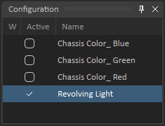
- Use the Edit button in the Properties panel to give a meaningful name to the new configuration. Name the Configuration "Revolving Light".
- Use the Save button to save the mechanism.
Adding Objects
In this section, we will add an object to a configuration.
- Click on the check box next to Revolving Light in the Configuration panel. The Properties panel of the configuration will become accessible.
- Click the Add button in the Properties panel. When the pop-up window appears, select the four extensions that comprise the revolving light in the Explorer panel, and confirm.
- Spot 1
- Spot 2
- Revolving Light Controller
- Connections Revolving Light
In the Properties panel of the configuration, set the Action on Activation drop-down menu to Add and Modify for all four objects.
Add means the object is added to a module and becomes managed only when the configuration is activated (i.e., checked).
Modify means that any changes to the object's properties will be saved while the configuration is active.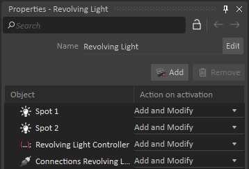
- Use the Save icon to save the mechanism.
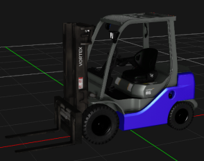
- In the Configuration panel, clear the check box. You will see that the yellow glow of the warning lights is gone. We still need to get rid of the revolving light model, however.
Modifying Objects
In this section, we will modify the behavior of an object when the configuration is active. In this case, we will change the visibility property of a graphic node.
- Make sure that the Revolving Light box in the Configuration panel is checked. We first need to expose the properties of the graphic nodes in order to include them in the configuration. This is done via a VHL interface.
- Open the forklift's Graphics Gallery by locating it in the Explorer panel and double-clicking on it.
- There should already be an interface present (to control the colors) in the Explorer panel. Double-click to display it.
- In the Explorer panel, locate the graphic node that comprises the revolving light (CHERRY_LIGHT):
- GLASS_DOME
- REFLECTOR
- LIGHT
- BASE
- BACK_GLOW
- CENTER_GLOW
- Select them all by holding Shift while clicking. In the Properties panel, click on the Visible input and drag it to the Inputs section of the interface. We will now be able to control the visibility of those nodes at the mechanism level.
- Use Save As to save a working copy of the Graphics Gallery in your Workshop Example folder. Do not check the Save as Copy box in the resulting dialog.
- Go back to the tab with the forklift mechanism. Select the Revolving Light configuration.
- Click the Add button in the Properties panel. When the pop-up window appears, select the Interface of the Graphics Gallery in the Explorer panel, and confirm.
- In the Properties panel, set the drop-down menu to Modify if not already set. This will allow you to change the properties of the object.
- Make sure the Revolving Light configuration is not checked, then select the Graphics Gallery's Interface in the Explorer panel, and uncheck the Visible boxes for the revolving light's graphic nodes in the interface's Properties panel. Any changes to the object's properties will be saved while the configuration is active (e.g., checked in the Configuration panel).
- Now activate the Revolving Light configuration.
- Click on the Graphics Gallery's Interface. Ensure that all the Visible boxes are checked.
- Use the Save icon to save the mechanism.
- In the Configuration panel, clear the check box. You will see that both the yellow lights and the revolving light model are gone. To bring it back, simply activate the configuration.
Removing Objects
In this section, we will add an object to a configuration, and set its action to Remove. We will also be using the right-button menu as a shortcut.
- In the Explorer panel of the forklift, locate the Human object in the Operator folder. Right-click on it.
- At the top of the menu, select Add to New Configuration. This will create a new configuration in the upper-left panel. Rename it to "Hide Operator".
- In the Properties panel, set the drop-down menu to Remove. The operator figure vanishes from the cab. Remove means the object is removed from modules and becomes unmanaged when the configuration is activated. Any changes to the object's properties will not be saved.
- Use the Save icon to save the mechanism.
- In the Configuration panel, clear the check box. The operator figure is back in his seat.
Activating Configurations
In this section, we will activate and de-activate our new configurations.
As long as there are no contradictions (e.g., one configuration adding an object at the same time another removes it), it is possible to have multiple configurations active at the same time.
- Click on the check boxes in the Configuration panel for the following configurations:
- Chassis Color_Blue
- Hide Operator
- Notice the changes to the mechanism:
- The chassis is now blue
- The operator is not present
- The revolving light is not present since its configuration is not active.
- Click on the check box in the Configuration panel for the Revolving Light configuration. A warning message appears – the Graphics Gallery's VHL interface is modified by both configurations, therefore they cannot be active at the same time.
- Press Continue to activate the Revolving Light configuration and deactivate the blue color configuration.
- Notice the changes to the mechanism:
- The chassis is back to its default color.
- The operator is still not present.
- The revolving light is present since its configuration is now active.
- Clear the check boxes in the Configuration panel. The mechanism returns to its default state (without the revolving light).
Inserting a New Scene Configuration
In this section, we will add a configuration to an existing scene.
- Go to the tab with the forklift scene. We will now create a Configuration to add objects to the scene.
- Select Simulation in the Toolbox. Double-click Configuration to create a new configuration.
- Use the Edit button in the Properties panel to give a meaningful name to the new configuration. Rename it to "New Boxes".
- Use the Save icon to save the scene.
Inserting Objects in a Scene Configuration
In this section, we will add objects to a scene configuration.
- In the Explorer panel, locate the "Movable_Crate" mechanism.
- Use Duplicate (Shift+D) to create two duplicates. Move them using the Move manipulator, so they become visible.
- Click the Add button in the Properties panel. When the pop-up window appears, select these three crates, and confirm.
- Movable_Crate
- Movable_Crate (3)
- Movable_Crate (4)
Setting Actions in a Scene Configuration
In this final section, we will set the actions of the objects in a scene configuration.
- We will now set the actions that the crates will be subject to when the configuration is active:
- Movable_Crate: Modify
- Movable_Crate (3): Add and Modify
- Movable_Crate (4): Remove
- Movable_Crate (3) has vanished, since it's set to Add and Modify and the configuration is not currently active.
- Click on the check box in the Configuration panel to activate the New Boxes configuration.
- Now that the configuration is active:
- Movable_Crate: no effect, since we didn't specify any change for its Modify action.
- Movable_Crate (3): is now present in the scene.
- Movable_Crate (4): has been removed from the scene.
- While the configuration is active:
- Movable_Crate: use the Move manipulator to change its position.
- Movable_Crate (3): do the same for this crate.
- Clear the check box in the Configuration panel. Notice that the crates return to their default state (with Movable_Crate (3) absent from the scene).
You should now be comfortable with the idea of Configurations and how they can be useful to optimize your scenes and mechanisms. For more reading on Configurations, click here.