Vehicle Presets Tutorial 1 : Creating a Wheeled Vehicle System
In this tutorial, you will learn the basics of the Vehicle Systems by modeling a simple eight-wheeled light armored vehicle (LAV).
The Vehicle Systems simplify creating a vehicle by automatically adding constraints and internal logic. Let's look at the basic components of the Vehicle Systems:
- Template: A set of components and logic modules that can be defined and saved to a template file to start the creation of a new vehicle. Vortex® comes with a number of preset templates for the most common vehicle configurations.
- Vehicle Components: Represent the mechanical parts of a vehicle, such as the engine, transmission, and wheels. Engine power flows through a set of connected components, while wheels and shafts move relative to the chassis.
- Vehicle Logic Modules: Control the behavior of a component.
Prerequisites
Before starting this tutorial, we recommend you have the Getting Started Tutorials covered first.
You must have Vortex Studio and the Vortex Studio Samples and Demo Scenes installed to be able to complete this tutorial.
You will start from an existing graphical asset from the Vortex Studio Demo Scenes installation directory. You will import a Graphics Gallery that already contains the 3D model. The default location is C:\CM Labs\Vortex Studio Content <version>\Demo Scenes\Equipment\Vehicle_LAV\Graphic, where <version> is the currently installed version.
Creating the Chassis
In this step, we import an existing Graphics Gallery into the Vortex Studio Editor and prepare the file for work by adding an assembly to receive the various parts and constraints.
Note In the recommended Vortex workflow, a 3D artist provides the Graphics Gallery and it already contains the required 3D model, along with its meshes, textures and graphics materials.
- Start the Vortex Studio Editor.
- Click on the Mechanism document type in the New Document section of the welcome screen to create a new mechanism.
- From the Explorer, click on the mechanism and rename it LAV Tutorial. Save (Ctrl+S) it to your working folder.
From the Graphics section of the Toolbox, select Galleries From Files.... Click on Browse and select LAV.vxgraphicgallery (...\Demo Scenes\Equipment\Vehicle_LAV\Graphic)
Note
You can create a copy of the Graphics Gallery in your working folder to make it possible to package and move the mechanism, because it is using a Relative Path to point to it.- Make sure that the graphics of the vehicle are located at the center (0, 0, 0) of the mechanism and facing the X+ axis.
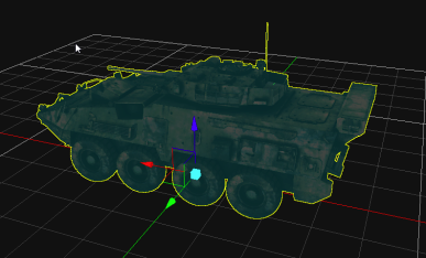
- From the Basics section of the Toolbox, add an Empty Assembly.
- Right-click on the LAV > LAV3_Stryker > LAV3_Stryker_Mesh graphics node in the Graphics Gallery and click Create Part.... In the resulting window, select Assembly from the Explorer panel.
Right-click on the newly created part and select Create Best-Fit Geometry > Convex Mesh..... Click Ok to generate the collision Geometry.
Note
You can open the assembly and rename (F2) this part Chassis to add clarity to the mechanism.- Double click on the part to open it. In the resulting window, click on Save All to save the assembly and the part files.
- In the Mass properties of the part, change its Mass to 15000.000 kg then click on Compute Inertia and COM
- Select the generated convex mesh collision geometry. Under Collision Detection, change its Material to Chassis.
- Save (Ctrl + S) and close the part.
Creating the Vehicle System
In this step, we will add a pre-generated vehicle template to the mechanism. The template contains a pre-set list of components and logic modules for a specific vehicle type, in this case a military 8x8 chassis (eight wheels, all powered).
- From the Vehicle Systems section of the Toolbox, insert the LAV 8x8 vehicle preset.
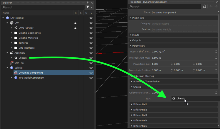
- Select the Dynamics Component of the vehicle then assign the Chassis part of the Assembly to the Part property of the Parameter > Chassis section.
Setting Wheels
- Type "radius" in the Search filter to find the radius information for all wheels. Set the Radius for all eight wheels to 0.55 m.
- Type "width" in the Search filter to find the width fields for all wheels. Set the Width for all eight wheels to 0.31 m.
- Type "mass" in the Search filter. Set the Mass of all eight wheels to 30 kg. Be careful not to overwrite the Internal Shaft Mass!
Type "steerable" in the Search filter. See that the four front wheels (Front Left Wheel, Front Right Wheel, Front Middle Left Wheel, and Front Middle Right Wheel) are set as Steerable.
Note
The Relative Position of the wheels also has to be set. In that case, the default values in the preset match the LAV model we are working on.- Open the automatically generated connection container named "Skin" from the explorer.
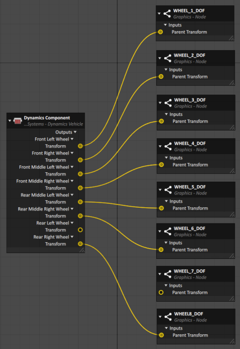
- Select the Dynamics Component of the Vehicle. Search for "transform" in the Search filter to find the Transform output field of all of the wheels.
- Drag and drop the Transform fields into the Connections Editor.
- Under the LAV Graphic Gallery, locate the graphics nodes of the wheels. Drag and drop their Parent Transform field into the Connections Editor.
- Connect the wheels Transforms from the Dynamics Component to the corresponding Parent Transforms of the wheels graphics nodes.
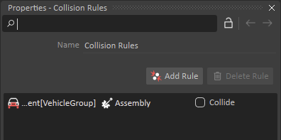
- From the Basics section of the Toolbox, insert a Collision Rule Container.
- Click on Add Rule. Drag Vehicle Dynamics Componentand the vehicle Assembly to its two fields.
Creating a Vortex High Level (VHL) Interface for Vehicle Controls
- From the Simulation section of the Toolbox, insert a VHL Interface.
- Rename (F2) it "Vehicle Controls".
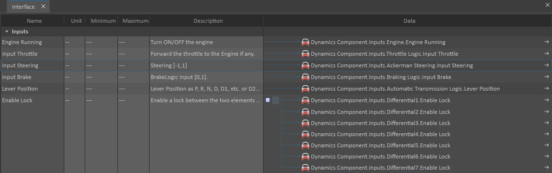
- From the properties of the Dynamics Component of the vehicle, insert the following inputs in the Inputs section of the VHL.
- Engine Running
- Input Throttle (under Inputs > Throttle Logic)
- Input Steering
- Input Brake
- Lever Position
- Enable Lock (under Inputs > Differential1)
- Search for "Enable Lock" in the properties of Dynamics Component. Drag the Enable Lock field from Differential[2-7] onto the last input in the list. This will allow to activate or deactivate all the locks at the same time.
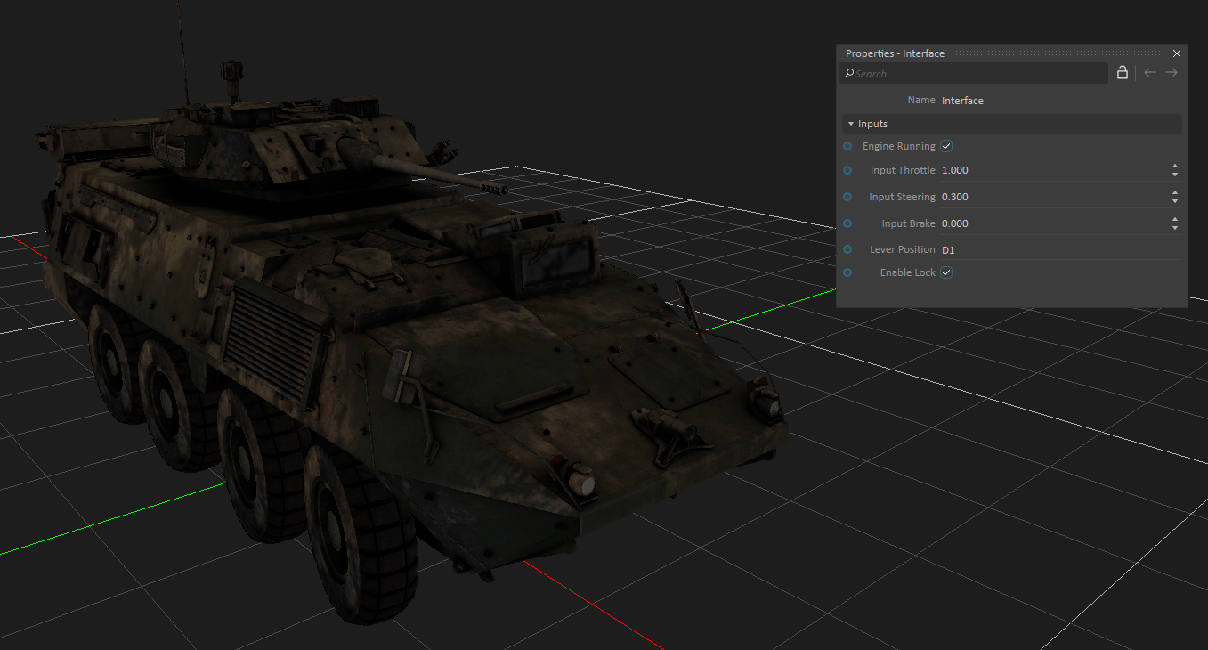
Start (F7) the simulation. Using the VHL, test your vehicle by changing the control values.
Note
If your vehicle is clipping through the ground, make sure the Grid is active. Right-click anywhere in the 3D Viewport, then select "Grid..." to access Grid Options, then select "Use Grid" and "Use grid as terrain"
Optional Challenges
Using what you learned so far, here are additional optional features that you can add to the vehicle. This part is not detailed in a step-by-step guide, so you will need to figure out the steps yourself.
Adding Dynamics to the Turret and Barrel
- Create parts for the turret and barrel. Their masses are 2000 kg and 200 kg respectively. Add simple collision geometry.
- Create motorized constraints that drive the yaw of the turret and pitch of the barrel.
- Create a VHL Interface for the inputs of the motors.
Adding Dynamics to the Antenna
- Create an assembly and parts for each sections of the antenna, weighing 100g each.
- Create constraints to the antenna and tune them so that it reacts to the movements of the vehicle (oscillating and stopping after a few seconds).