Modular Vehicles Tutorial 2: Creating a Vehicle from a Template
Now that our Vehicle Template is fully configured, we can use it to create a Vehicle Mechanism. In this section, we'll create a Chassis Assembly and add Graphics, as well as tuning the powertrain of the AWD8x8.
Prerequisites
Modular Vehicles Tutorial 1: Creating a Vehicle Topology
Creating the vehicle file structure
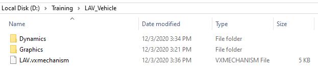
- Create a folder for your vehicle mechanism. For the LAV, let's name it "LAV_Vehicle"
- Create a Graphics folder. Copy the LAV.vxgraphicgallery from the Demo Scenes (C:\CM Labs\Vortex Studio Content <version>\Demo Scenes\Equipment\Vehicle_LAV\Graphic) to this folder.
- Create a Dynamics folder. Insert the FWD_8x8 template folder created in the last tutorial into it.
- In Vortex Studio, create an Assembly. Save it in the Dynamics folder and name it LAV_Chassis.vxassembly.
- Create a mechanism. Save it in the LAV_Vehicle Folder and name it LAV.vxmechanism.
Editing the Chassis Assembly
- Open the LAV.vxmechanism.
- Insert LAV.vxgraphicgallery to the mechanism using Galleries From Files in the Graphics section of the Toolbox.
- Insert LAV_Chassis.vxassembly to the mechanism using Assemblies From Files in the Basics section of the Toolbox. Rename it "Chassis Assembly" in the Explorer.
- Under the Graphics Gallery, right click on LAV3_Stryker_Mesh and Create Part in... to create a part in the Chassis Assembly.
- Create a Convex Mesh Collision Geometry by right-clicking on the part.
- Repeat for BARREL_DOF, ANTENNA_1_DOF and TURRET.
- Open the Chassis Assembly.
Rename, set the Mass and reset the Inertia of the parts using the values in the table below:
Original Part Name NewPart Name Mass (kg) LAV3_Stryker_Mesh Chassis 12,500 TURRET Turret 2,000 BARREL_DOF Barrel 200 ANTENNA_1_DOF Antenna 1 Set the Material of all of the part collision geometries to Chassis.
Create the following constraints:
Type
Part 1 (Reference)
Part 2
Position
Primary Axis (Part 1)
Secondary Axis (Part 1)
Control Hinge Turret Chassis -1 m; 0 m; 2 m +Z: 0 m; 0 m; 1 m +Y: 0 m; 1 m; 0 m Locked Hinge Barrel Turret 0 m; 0 m; 0 m +Y: 0 m; 1 m; 0 m +X: 1 m; 0 m; 0 m Locked Universal Antenna Turret 0 m; 0 m; 0 m +Y: 0 m; 1 m; 0 m +X: 1 m; 0 m; 0 m Locked with 50 N.m/rad and 0.5 kg.m2/s
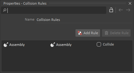
- Set a Collision Rule for the whole assembly to not collide.
- Right-click on the Chassis part and Insert Attachment Point. Rename it Chassis_Vehicle_Attachment
- Save the Assembly.
Adding the Vehicle Template
- Insert AWD_8x8.vxassembly to the mechanism.
- Open the Skin Connection Container (automatically created previously).
- Insert the Wheel Transform Output from the Wheel Transforms Interface of each wheel of the AWD_8x8 assembly into the Connections Editor.
- Insert the Parent Transform Input from each Wheel Graphic Nodes of the LAV Graphics Gallery.
Connect the Inputs to the corresponding Outputs. The Wheels transforms should be inserted in the ascending order from 1 to 8.
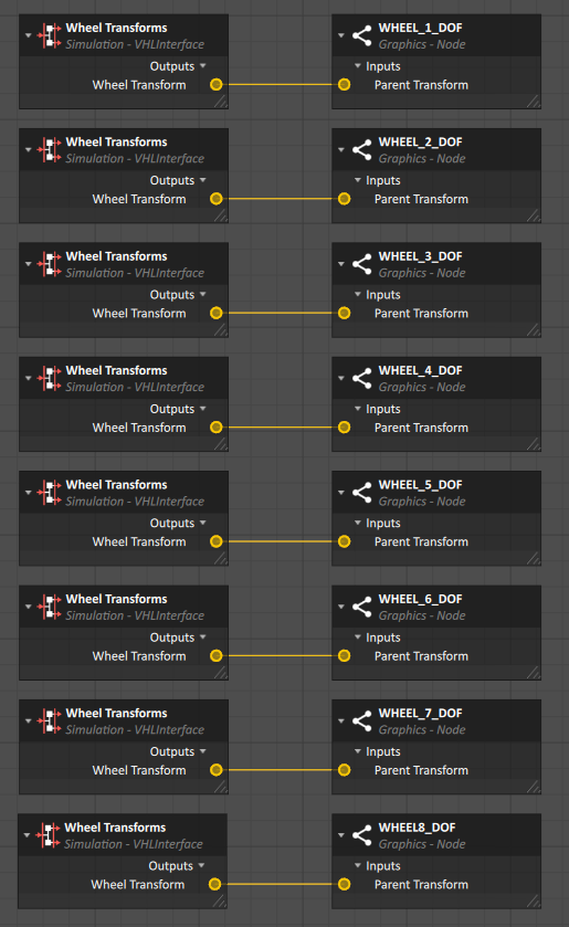
The order goes (from 1 to 8): FL, FR, FML, FMR, RML, RMR, RL, RR.
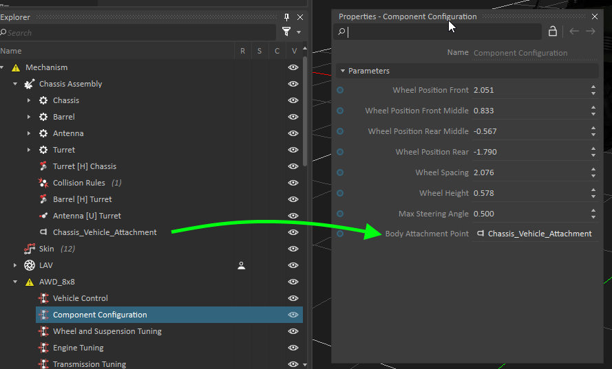
- Assign the Body Attachment Point Parameter of the Component Configuration Interface to Chassis_Vehicle_Attachment found under the Chassis Part.
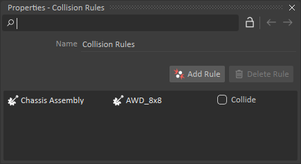
- Insert a Collision Rule Container and add a rule between Chassis Assembly and AWD_8x8 for no collision.
Setting up the Wheels
- Under the Template Assembly, select the Wheel and Suspension Tuning VHL.
- Set the following properties:
- Radius : 0.569 m
- Width : 0.300 m
- Mass : 228.5 kg
- Suspension Stiffness : 160,000 N/m
- Suspension Damping : 20,000 kg/s
- Tire Stiffness : 180,000 N/m
Tuning the Engine
- Create a Resources in your vehicle folder structure.
- Find LAV_TT.csv and LAV_BTT.csv from "Vortex Studio Content <version>\Demo Scenes\Equipment\Resources\VehicleSystems". Copy those files in the Resources folder you just created.
- Under the Template Assembly, select the Engine Tuning VHL.
- Set the following properties:
- Shaft Mass : 10 kg
- Shaft Inertia : 1 kg.m2
- Torque Table : LAV_TT.csv
- Braking Torque Table : LAV_BTT.csv
Tuning the Torque Converter
- Under the Template Assembly, select the Torque Converter Tuning VHL.
- Set the following properties:
- Stall RPM : 1,800 RPM
- Stall Torque : 1,600 N/m
- Shaft Mass : 10 kg
- Shaft Inertia : 1 kg.m2
Tuning the Transmission
- In the Resources folder, create a CSV file named "Automatic Transmission Ratios.csv
Fill the file with values from this table:
-6 -5 -4 -3 -2 -1 0 1 2 3 4 5 6 7 8 -14.5 -10 -6.6 -4.9 -3.33 -2.309 0 9.57 6.635 4.37 3.219 2.188 1.517 1 0.736 - Set the following properties:
- Gear Ratio Table : Automatic Transmission Ratios.csv
- Shaft Mass : 10 kg
- Shaft Inertia : 1 kg.m2