Cables Tutorial 2 : Creating Hooks and Loops
In this tutorial, you will learn how to use hook and loop groups to attach and detach objects during runtime. We will define attachment points, create hook and loop groups, and define the logic required to connect and disconnect them following user input.
For more information, refer to the documentation about Hook and Loop Groups.
Requirements
This module assumes that Cables Tutorial 1: Creating a Cable System is completed and you have a functional mobile crane with a cable system. If this module is not completed, you can use the mobile crane.vxmechanism located in the samples (<Vortex Demo Scenes Folder>\Equipment\MobileCrane\Dynamic\Design\mobile crane.vxmechanism) and skip steps 1-6.
Adding Attachment Points
In this step, we will add attachment points to the mobile crane's hook, the spreader bar, and the concrete pipe. These will be used to determine the location of the attachment(s) between the mechanisms.
- Open the Mobile Crane mechanism completed in Cables Tutorial 1: Creating a Cable System
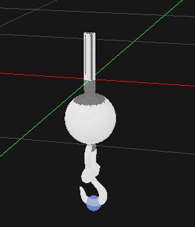
- Under the Assemblies folder in the Explorer, open the Weight Hook assembly by double-clicking on it.
- In the Dynamics section of the Toolbox, insert an Attachment Point. Rename it 'Hook Attachment'
Under Parameters in the Hook Attachment properties, set the Parent Part to Hook Shackle.
Note
The more efficient way to add an attachment is to right-click on the parent part in the explorer, then selecting "Insert Attachment Point" from the contextual menu.- Under Inputs, modify the translation component of its Local Transform to [-0.017 m, 0.000 m, -0.329 m]
- Save (Ctrl + S) and close the Weight Hook assembly.
- Open the SpreaderBar_Rigging_Workshop mechanism (<Vortex Sample Folder>\Equipment\SlingCable\Dynamic\Design\SpreaderBar_Rigging_Workshop.vxmechanism)
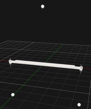
- Open the SpreaderBar assembly.
- Insert an attachment point to each of these parts :
- Loop
- Hook_Rear
- Hook_Front
- Rename the attachments Loop_att, Hook_Rear_att, Hook_Front_att. Keep the translation component of their local transform at [0,0,0]
- Save (Ctrl + S) and close the SpreaderBar assembly.
- Open the Concrete Pipe Large_Workshop mechanism (<Vortex Demo Scenes Folder>\Equipment\SlingCable\Dynamic\Design\Concrete Pipe Large_Workshop.vxmechanism)
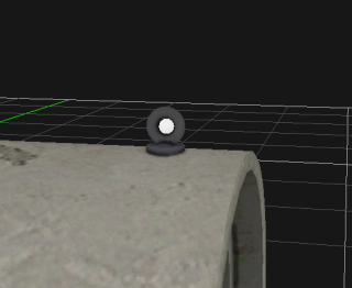
- Open its assembly (Concrete Pipe Large_Workshop_Assembly.vxassembly).
- Insert two Attachment Points to the only part in the assembly :
- Pipe_Front [4.123 m, 0.000 m, 1.128 m]
- Pipe_Rear [-4.179 m, 0.000 m, 1.114 m]
- Save (Ctrl + S) and close the Concrete Pipe Large assembly.
Defining Loop Groups
In this section, we define loop groups for the concrete pipe and the spreader bar. A loop group and a hook group that have the same label can be attached to each other.
Note
- Open the Mobile Crane Workshop scene (<Vortex Sample Folder>\Scenario\MobileCrane Scene\MobileCrane Weight Hook Pipe_Workshop.vxscene)
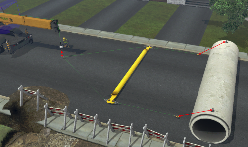
- Insert the Mobile Crane, SpreaderBar_Rigging_Workshop, and Concrete Pipe Large_Workshop mechanisms in the scene. Those are the three mechanisms to which we added attachment points in the previous section.
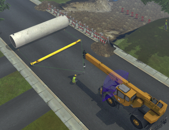
- Using the Move (Ctrl + 2) and Rotate (Ctrl + 3) tools, place them in the scene to match the layout shown in the image :
- In the Dynamics section of the Toolbox, insert a Loop Group. Rename it "Pipe Loop Front".

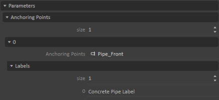
- Under Parameters > Anchoring Points, change the size to 1.
- Set the Anchoring Point to the Pipe_Front attachment point, found in the Concrete Pipe Large assembly.
- Under Labels, change the size to 1. Name the label 0 to "Concrete Pipe Label"
- Duplicate (Ctrl + D) the Loop Group and rename it "Pipe Loop Rear"
Change the Anchoring Point to the Pipe_Rear attachment point, found in the Concrete Pipe Large assembly.
Note
Notice that the label remains the same in both loop groups. We will use the same label for both hooks from the spreader bar and both loops from the concrete pipe. This way, hooking will be possible even if the spreader bar is turned around and the hooks are inverted.- Repeat steps 4 to 7 for the Spreader Loop Group using these values:
- Name: "Spreader Loop"
- Anchoring Point: Loop_att, under the SpreaderBar assembly
- Label: "Spreader Label"
Defining Hook Groups
In this step, we define hook groups for the spreader bar and the mobile crane hook block.
- In the Dynamics section of the Toolbox, insert a Hook Group. Rename it "Spreader Hook Front".

- Under Parameters > Anchoring Points, change the size to 1.
- Set the Anchoring Point to the Hook_Front_att attachment point, found in the SpreaderBar assembly.
- Under Labels, change the size to 1. Name the label 0 to "Concrete Pipe Label"
- Duplicate (Ctrl + D) the Hook Group and rename it "Spreader Hook Rear"
- Change the Anchoring Point to the Hook_Rear_att attachment point, found in the SpreaderBar assembly.
- Repeat steps 1 to 4 for the Mobile Crane Hook group using these values:
- Name: "Mobile Crane Hook"
- Anchoring Point: Hook Attachment, under the Weight Hook assembly of the Mobile Crane.
- Label: "Spreader Label"
- Save (Ctrl + S) the scene.
Adding Hooking Logic
In this section, we will add logic that attaches our different hook and loop groups together when pressing buttons on the controller.
- In the Input Devices section of the Toolbox, insert a Joystick.
- In the Basics section of the Toolbox, insert a Connection Container. Rename it "Connections - Hooking"
- Open the Connection Container. Select the Joystick from the Explorer and drag-and-drop ToggleButton2 and ToggleButton3 into the Connections Workspace.
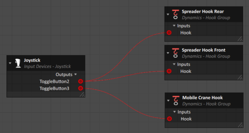
- Select the three Hook Groups previously created and insert the Hook input into the Connections Workspace.
- Connect ToggleButton2 with both Spreader Hook inputs and ToggleButton3 with the Mobile Crane Hook input.
- Test (F7) the simulation. Notice the colors of the attachments change depending on the distance between hook and loop groups and whether a hook is triggered.
Tuning Hooking Parameters
In this section, we will tune parameters in order to make it easier for the user to hook and unhook components during runtime.
- Select the Loop Groups (Pipe Loop Front, Pipe Loop Rear, Spreader Loop Group) and access their properties.
- Under Inputs, modify the Hooking Range to 0.75 m and Extended Range to 0.25 m.
- Select the Hook Groups (Spreader Hook Rear, Spreader Hook Front, Mobile Crane Hook) and access their properties.
- Under Inputs, deselect Always Allow Unhooking.
- Under Parameters > Hooking Constraints, modify the following properties:
- Attract Max Force: 5000 N
- Attach Distance: 0.015 m
- Detach Force: 500 N
- Save (Ctrl + S) the scene.