Cables Tutorial 1 : Creating a Cable System
This tutorial includes video content:
In this tutorial, you will learn how to use the Cable Systems add-on by adding a cable to an existing mechanism and altering the physical parameters of the cable system.
Cable systems can be part of mechanisms and scenes. They can be used to model specific cables in cranes and vehicles, and carry out hoisting, lifting, and dropping operations.
For more information about Cable Systems, see:
Prerequisites
Before starting this tutorial, we recommend you have the Getting Started Tutorials covered first.
You must have Vortex Studio and the Vortex Studio Demo Scenes installed to be able to complete this tutorial.
The cable system is created using a mobile crane assets from the Demo Scenes content. The default location is C:\CM Labs\Vortex Studio Content <version>\Demo Scenes\MobileCrane\Dynamic\Design, where <version> is the currently installed version.
Add a Cable System to an Existing Mechanism
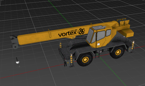
In this step, we start from an existing mechanism (in this case, a mobile crane) and add a cable system to it.
- Locate and open mobile crane no cable.vxmechanism.
- To better see the crane in the 3D View, right-click in the 3D View and deselect Debug Display > Geometry.
- In the Cable Systems section of the Toolbox, insert a Generic Cable.
- Save As to create a copy of the mechanism in your work folder.
Creating the Cable
In this step, we create the cable itself by defining the number of point it goes through, i.e., the number of times it changes direction.
- Select the Dynamics Generic Cable extension under the new Generic Cable element in the Explorer panel.
- In the Dynamic Generic Cable's Properties panel, set these fields in Parameters > Definition > Param Definition:
- Material Name: Chassis
- Geometric radius: 0.005 m
- Geometric Stiffness Enabled: true
Parameters > Definition > Point Definitions, change the size to 4.
Note
The cable will go through four points: the winch, two pulleys at the tip of the crane boom, and an attachment on the hook.- Save (Ctrl + S) the mechanism.
Configuring Cable
In this step, we configure the various cable touch points to correspond to the mechanical devices on the real crane. This is done in the Point Definitions we just created in the previous step.
- Return to the Dynamics Generic Cable properties, under Parameters > Definition > Points Definitions.
Set each points properties to the values in the table below:
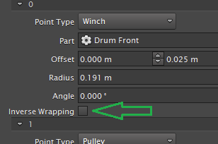
Connection Point Point Type Part Offset 0 Winch Assemblies > Mobile Crane > Parts > Drum Front [0, 0, 0] 1 Pulley Assemblies > Mobile Crane > Parts > Boom Pulley Top L [0, 0, 0] 2 Pulley Assemblies > Mobile Crane > Parts > Boom Pulley Bottom [0, 0, 0] 3 Attachment Point Assemblies > Weight Hook > Block Top [0, 0, 0.22] 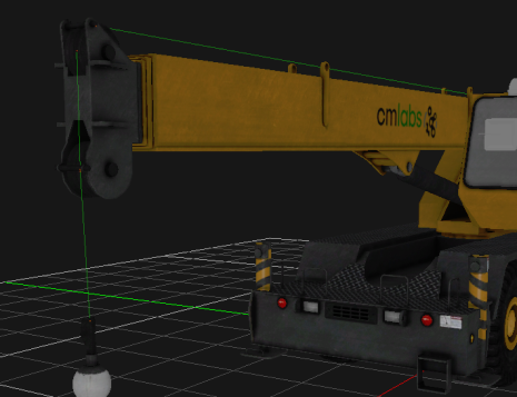
- Test (F7) the mechanism. Make sure that the cable is wrapped around the connection points correctly. If not, use the Inverse Wrapping property.
Adjusting the Cable
In this step, we modify various parameters to adjust the behavior of the cable, making it flexible yet strong like a real steel cable should be.
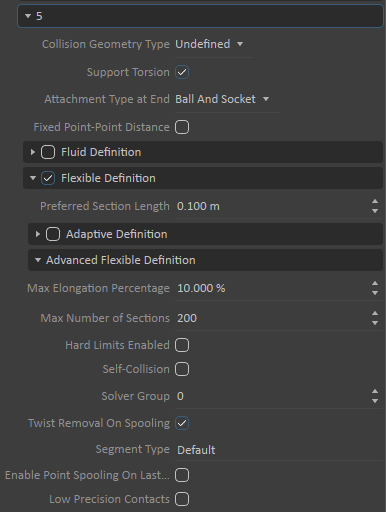
- Expand the Parameters > Definition > Segment Definitions section in the Dynamics Generic Cable's Properties panel. Under Segment 5, change the following:
- Collision Geometry Type: Capsule.
- Attachment Type at End: Fixed
- Flexible Definition: True
- Preferred Section Length: 0.1 m
- Preferred Section Length: 0.1 m
- Select the Dynamics Properties extension under the Generic Cable element. Under Inputs, set the various fields to these values:
- Relative Elongation: 0.02
- Load: 300000
- Young's Modulus: 110
- Cable Diameter: 0.02
- Number of Wires: 5
- Density Unit: Linear Density
- Density: 2.5
- Under Scaling Factors, set the various fields to these values:
- Bending Stiffness Scale: 0.5
- All other Scaling Factors: 1
- Test (F7) the mechanism. Using Alt + Left click, move the hook around and observe if the cable bends.
- Save (Ctrl + S) the mechanism.
Configuring Cable Graphics
In this step, we set a graphic material to give a proper visual appearance to the cable (by default, cables with no assigned graphic material are flat white).
- Select Graphics Cable under the Generic Cable in the Explorer panel.
- Under Inputs, set the input Graphics Material to CableSteel_Mat.
- Under Parameters, set the various fields to these values:
- Radius: 0.005
- Interpolation: True
- Texture Repeat Length: 5
- Subdivision per Section: 2
- Test (F7) the mechanism. The cable should now have a metallic appearance.
- Save (Ctrl + S) the mechanism.