Vortex Studio Content Starting Guide
- DEVOPS
How to Install and Use Vortex Studio Content
The Demo Scenes and Samples are part of the Vortex Studio package, available from the Downloads page of your CM Labs account.
To install Vortex Studio:
- Go to your account on the CM Labs website
- On the login page, enter your username/email and password.
- Select the Downloads link on the left-hand of the page.
- Download the Vortex Setup application
- Once the download is completed, start the Vortex Setup application and follow the installation process. Please select all the components available for a complete experience.
Demo Scenes Directory Structure
The Demo Scenes folder can be found under the CM Labs installation, in the /Vortex Studio Content <version> folder.
The Scenario folder contains the actual scene files, which link to the required mechanisms and objects in the other folders.
Sub-directory | Contents |
Environment | Terrains used in scenes |
Equipment | Vehicle and prop mechanisms |
| localization | Translation in other languages |
Materials | A graphics gallery containing a wide variety of preset materials |
| Resources | Configuration used when starting simulator using Vortex Director |
Scenario | Demo scenes to load in Vortex Player and Vortex Editor |
| Training | Assets used in tutorials |
Verification | Python scripts demonstrating Vortex scripting for vehicles verification |
Samples
The Samples provide a collection of simple mechanisms representing objects found in an urban and construction environment. They have been built in the Vortex Studio Editor from a Graphics Gallery and have collision geometries to match. They consist of generic buildings and objects that would be found on the streets. You can use and redistribute them in any Vortex scene or simulator you create. 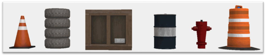
The samples include prebuilt vehicles ready for simulation. They feature improved high-level interfaces exposing the most important controls and parameters. This allows you to configure and interact easily with the vehicle, without having to learn the complex implementation of the components. More advanced parameters and inputs allow you to completely customize your vehicle.
Building and test-driving different versions of your vehicle is as easy as replacing the assemblies. The Vortex Studio Editor will re-connect all the data paths automatically. 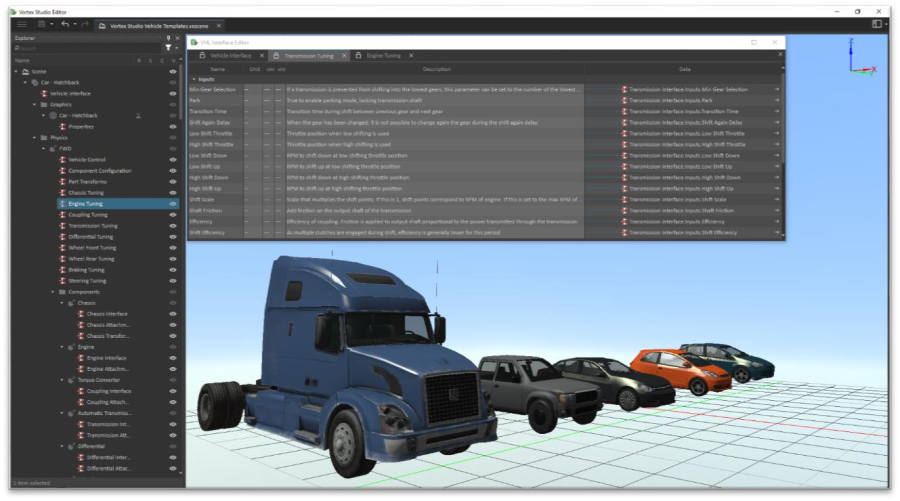
This version of the Vortex samples features a collection of ships modeled with the XRI toolkit from Marin Institute®. You can take advantage of the advanced hydrodynamic simulation features by using these sample vessels on an Ocean extension in a Vortex scene. 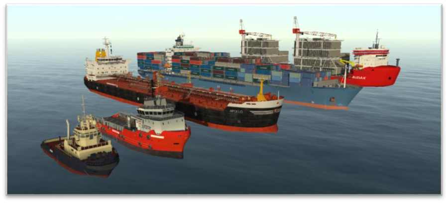
The ships require the Hydrodynamics module to be present in your setup. See Vessel Simulation with MARIN XRI
Starting a Simulator with Vortex Studio Director
Double click on the Vortex Studio Director icon on your desktop.
From the Tools menu, open the Settings... to select the location of the simulator files.
The simulator files for the Demo Scenes are in the Resources/config folder of the installed Vortex Studio Demo Scenes, typically: C:/CM Labs/Vortex Studio Content <version>/Demo Scenes/Resources/config
Select the 01_Console_Operator simulator and Launch it.
Vortex Studio Console starts up with the Excavator equipment selected, see 2810160536 for more details.
Other resources in Vortex Demo Scenes with Vortex Studio Director
Three sample simulator files are included with the Vortex Demo Scenes:
- 01_Console_Operator
- 02_Console_Instructor
- 03_Console_Operator_Instructor
01_Console_Operator and 02_Console_Instructor are single-user simulators designed to be used on a single computer.
03_Console_Operator_Instructor represents a dual-user simulator requiring at least two networked computers. To be able to launch it successfully:
- Edit the 03_Console_Operator_Instructor simulator definition
- Select an available networked computer as the host for the Console.Instructor application
- Save the modified simulator
- Launch
Simulate Content in Vortex Studio Player
Double click on the Vortex Studio Player icon on your desktop.
This main window is the interface used to load content and get information about your simulation: 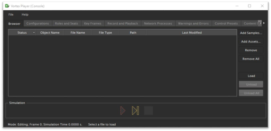
Any Vortex file (*.vxscene, *.vxmechanism) can be drag and dropped from a file browser directly inside the browser tab of the window: 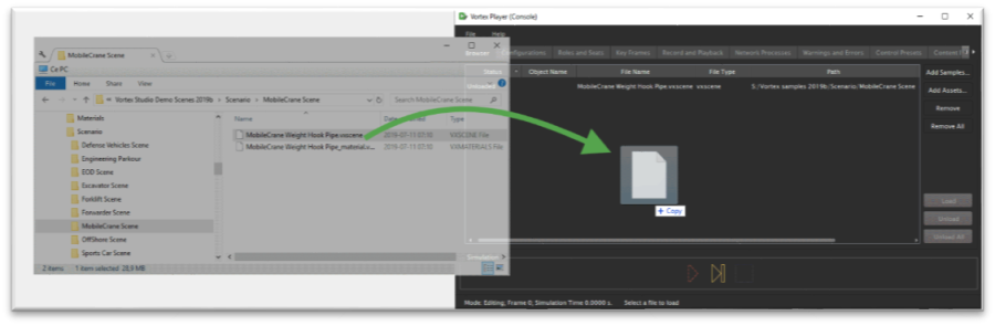
Double click on an object in the browser list to load it in memory. It will then be ready for simulation
Scenes have different cameras and roles — usually a default, free-fly camera and additional cameras attached to vehicles. Select a role to enable the controls associated with that role, and select the camera associated with the role to get the correct viewpoint (respectively "r" and "c" keyboard keys in the graphics 3D window)
Alternatively, use the Roles and Seats tab in the Player to activate a specific role (click on the "Roles" column entry and select a role from the drop-down menu).
Edit Content in Vortex Studio Editor
Double click on the Vortex Studio Editor icon on your desktop.
Open files using the menu in the editor.
Once the file is loaded, you can navigate the content and see how it was done.
Scenes have different cameras and roles — usually a default, free-fly camera and additional cameras attached to vehicles.
The Vortex Studio Editor has a different behavior when it comes to roles. The editor is its own seat, and by default, if no role is activated, it is as if all the roles were active at once, allowing the user to use everything.
This leads to some side-effects, like controlling all vehicles at once and having HUDs overlap, for example.
You can activate a single role to simulate the same behavior on a simulator.
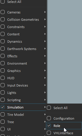
- (optional)Filter the explorer view to only show roles, click on the funnel icon, and select Simulation → Role
- Locate the role you want to activate.
- Right-click on the desired role and select Activate
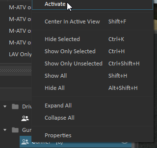
- Each time a role is activated, the previous one is deactivated automatically
A role can also be deactivated following the same steps. The activate option will read deactivated if the role is active.
Demo Scenes Scenarios
See also 2810160536
The Scenario folder contains the actual scene files, which link to the required mechanisms and objects in the other folders.
The Vortex Demo scenes require a gamepad device to control the different vehicles. If you have a different type of control device, you might need to adjust the connections and mapping using the Vortex Studio Editor. However, you can navigate through the 3D space using the mouse in combination with the Q, W, E, A, S, and D keyboard keys. Navigation is also possible when the simulation is running.
Scene Description
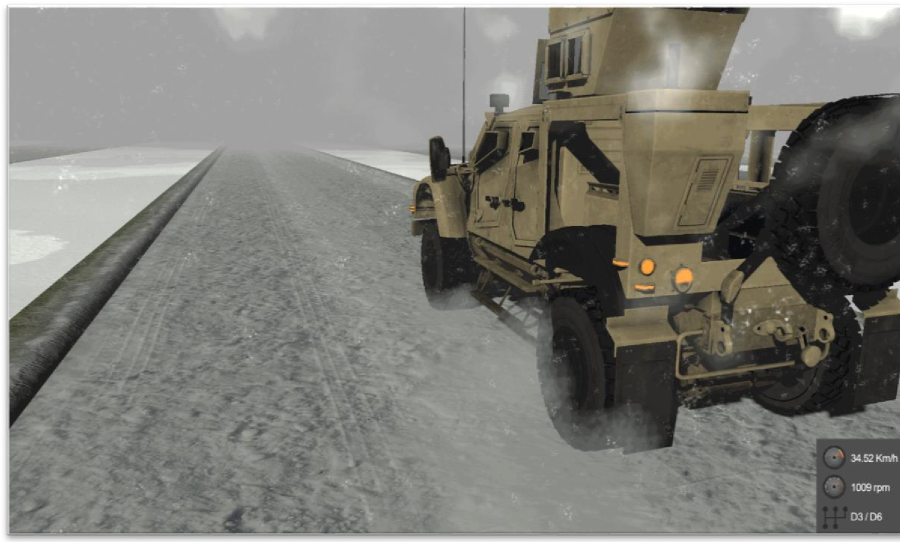
Defense Vehicles | This scenario includes a group of armored vehicles that can be driven over a variety of terrain types. |
Mobile Crane | This scenario features a rough terrain crane lifting concrete pipes from a flatbed trailer in a constrained environment (houses, trees). A second configuration features a spreader bar used to lift longer concrete pipes. |
Offshore (Top Side) – Vessel with Knuckle-Boom Crane | This scenario features an intervention vessel using a knuckle crane to lift an EDP out of the water and onto the deck. |
Offshore (Sea Bed) – Subsea Field with ROV | The same Offshore scenario features a generic remotely operated vehicle inspecting a typical subsea field. The ROV is equipped with controllable arms and is connected to the intervention vessel through the feeder cable. |
Excavator and Dump Truck | This scenario shows a standard 36-ton excavator digging and filling a dump truck with soil in a construction zone. |
Explosive Ordnance Disposal | This tense night scenario shows an EOD specialist using a tethered Packbot to inspect and move a suspicious suitcase. |
Forklift in Warehouse | This scenario features a forklift moving boxes and pallets from one set of shelves to another. |
Forestry Forwarder | This outdoor scenario features a heavy forestry forwarder collecting piles of logs and stacking them on flatbed trailers |
Engineering Test Terrain | This scene is an empty plain with modular terrain elements used to build your own custom test track. |
Materials Gallery
Unlike the other scenes, this one is a graphics gallery. It contains a number of preset, specular graphics materials, such as metal and plastic.
Note: some of the scenes include features and systems that might not be available under your Vortex Studio license. If this is the case, not all functionalities of the scene will be available, and warnings may appear in the Editor. Please contact a CM Labs Account Manager to inquire about the different licensing options.
An HTC Vive or HTC Vive Pro head-mounted display can be used in any simulation featuring a Viewpoint or Camera. Refer to the Vortex Studio documentation, under the Head-mounted Display topic.
Defense Vehicles
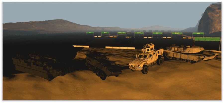
This scene provides a number of simulated combat units: Two eight-wheeled Light Armoured Vehicle (LAV), with and without Hull Protection Kit (HPK, heavy armor which reduces maneuverability), and MATV wheeled transport and an M1A2 main battle tank.
Highlights
- The LAV features a semi-automatic transmission with 14 gears (6 reverse and 8 forward speeds).
- The LAV driver can engage the 8x8 mode by locking all differentials for increased all-terrain performance.
- Flat tire faults can be triggered by the Instructor VHL Interface of the LAV.
- Both the LAV and M-ATV include tire models for hard and soft surfaces.
- The M-ATV has an automatic transmission that can be overridden by the driver.
- The M-ATV has multiple driving modes: 2WD, 4WD, and 4WD with locked differentials.
- The M1A2 features an automatic transmission with a pivot gear to turn on the spot.
- The turrets can be controlled via the D-pad. It is possible to fire the main gun with blank ammunition, with a recoil effect.
- All vehicles of the scene use the multi-texturing feature. The LAV has textures for different levels of dirt and mud, which can be linked to the odometer (the vehicle gradually gets dirtier).
- The LAVs and M-ATV leave a dust trail when moving across certain types of terrain.
Operation Notes
- Before starting the simulation, you can activate a mechanical configuration to remove the LAV's turret.
- The vehicles can be driven from either position (driver or gunner), only the viewpoint changes.
- Put the vehicle in gear and use the throttle to start moving.
- Flat tire faults can be triggered from the Instructor VHL Interface for the LAV.
Simulation Notes
- The Scene Configurations panel includes several different starting points for the vehicles.
- The antenna's graphic model is divided in five pieces. Parts connected with hinge constraints are used to create the flexible antenna.
- The wheels of the LAV and M-ATV have specific Tire Models for a simulated response on different terrain types.
- Two cameras are placed in the mechanisms to provide independent points of view for the operators (driver and gunner).
- A viewpoint extension is placed in the mechanisms for use with multiple displays (refer to the documentation under the Displays and Viewpoints topic).
- The Vehicle Systems use braking and engine torque tables that are suitable for heavy equipment. Additional tables are available in the Equipment/Resources folder.
- Each wheel of a vehicle can be defined as 'steerable'. The LAV's four front wheels are configured as such.
- The models use the latest Vehicle Systems features: transition time between the gears, maximum torque on differential locks, and minimum and maximum travel of the suspension.
- The HPK Armor is a separate mechanism that is attached, at the scene level, to another instance of the base LAV model. Note that both armor and vehicle have corresponding attachment points set up at the mechanism level.
- The LAV also has four Attachment Points on the chassis corners that can be used to hook towing cables and other equipment.
- The LAV and M-ATV have a script and particle emitters that use the "Material in Contact" wheel output to drive the emission of dust particles of a color matching the ground material.
- The LAV model uses the multi-texturing feature to present both a clean and dirty appearance. By modifying the alpha value of the layers, it's possible to progressively dirty up the vehicle (either by manual control or via a script).
Python Scripts
- Differential Lock handles which differential components are locked. Note that the two rear axles are locked permanently on the LAV (this can be changed in the differential script).
- Gear Value returns the exact gear mode and number for the VHL output interface.
- LAV Controller handles the gear (Park, Gear Up, and Gear Down) and engine state of the vehicle. It takes various inputs such as current gear, throttle, and brake signals (either from the VHL or another script), and returns values to the Vehicle Systems to put the LAV in motion.
- Recoil applies forces similar to the ones generated when firing the gun if the "fire" button is pushed on the gamepad.
- Turret Controller controls the turret's motions using switch inputs rather than analog since the turret is controlled from the digital D-Pad instead of an analog joystick.
- Inline Help manages the display of the joystick control diagram in the lower-left corner of the screen.
- Dust and Splash Logic looks at the vehicle's speed and the wheels' Material in Contact output, and use the two to control a pair of particle emitters attached to the rear wheels. The particles are emitted at a rate proportional to the vehicle's speed and with a color matching the ground currently in contact with the wheels.
- M1A2 Controller handles the gear (Park, Gear Up, and Gear Down) and engine state of the vehicle. It takes various inputs such as current gear, throttle, and brake signals (either from the VHL or another script), and returns values to the Vehicle Systems to get the tank in motion. Pivot Steer is available to turn the tank on the spot.
- Tire Pressure Logic controls the pressure in the tires depending on the driver's selected mode.
- ABS and TC Logic simulates the presence of anti-lock brakes and a traction control system.
- Spring Compression Display Logic is used to visually deform and compress the spring models in the suspension of the M-ATV.
Mobile Crane
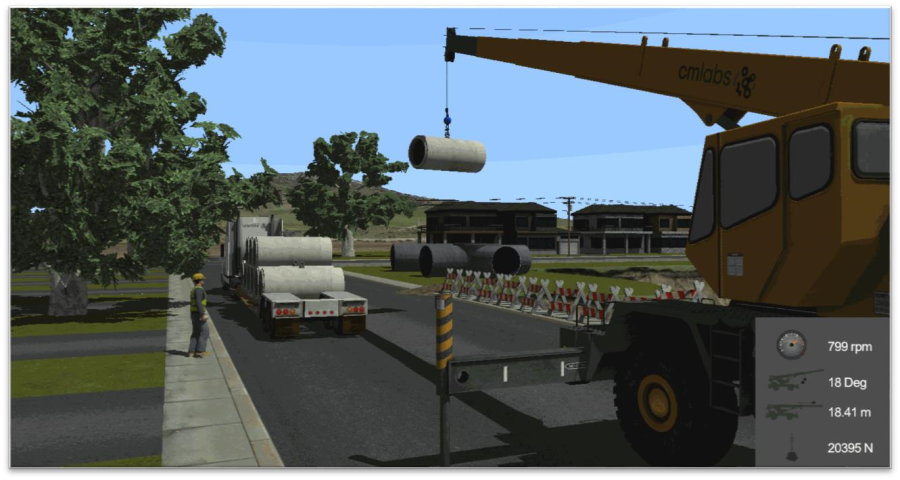
This sample provides an example of a typical rigging scenario: a mobile crane has been set up in a suburban construction field where it is used to unload and move sections of concrete pipes. The model combines Vehicle Systems with Cable Systems and advanced logic.
Highlights
- Cable Systems for both the mobile crane and the spreader bar.
- Rigging is simulated via a Hooking extension to attach the hooks and loops as needed.
- The hydraulic systems are simulated via a Python script with a low-pass filter to provide a feel similar to the real vehicle.
- The Vortex Studio Human library is used for all avatars present in the scene, including the slingers and supervisor.
- The trees and other vegetation come from the Vortex Studio Vegetation library.
- Configurations at the Scene level are used to model three different starting situations: unloading a transport truck, using a spreader to lift a wide load, and dangerous over-extension.
- All components of the scene use the multi-texturing feature. The terrain is a Graphics Gallery.
Operation Notes
- While the featured model includes the crane's normal driving capabilities, the scene's scenario locks the crane in operation mode for simplicity.
Note: The crane will not accept commands until the outriggers are fully deployed.
- The engine throttle must be used in combination with the respective hoist, boom, and turret commands.
- The D-pad can be used to control the point of view of the operator.
- The scene uses color-coding to indicate the state of the rigging. The hook and slings must be brought close to one another to allow them to be attached.
- If the hook is red, the Anti-Two Block is activated; the hook is too close to the boom's pulley. You must lower the hoist.
- If the hook is green, you are in range to attach the load's sling to the hook. Make sure the hook is properly positioned above the load.
- If the hook is yellow, the load is being attached. Do not move the crane or hook.
- A blue hook means that the load is properly attached.
- The truck and trailer can be backed up to get them closer to the crane for unloading. Make sure the truck driver's Role is active or you will not be able to drive it!
Simulation Notes
- The mobile crane assembly includes some features to increase the fidelity of the model, such as:
- The hydraulic controls (turret, boom elevation, and extension) are matched with a low pass filter to add inertia.
- The turret and booms have some relaxation in their constraints to provide torsion under heavy lifting. o The weighted hook contains a hinge constraint with friction to avoid torsion when the load is rotating. Cable Systems has the Enable Breakage parameter turned on.
- When the maximum tension (50,000N) is exceeded for more than 120 steps (approx. 2 seconds), the crane's cable is cut.
- The Hooking extension adds a constraint between each sling cable attachment point and the hook attachment point. This operation is performed when the simulation is started. When the hook is within the attraction distance and the "attach" command is triggered, the Max Force value is applied to attract the sling attachment point onto the hook progressively.
Python Scripts
- Anti-Two Block measures the distance between the hook and the pulley and locks the drum if they are too close.
- Drum takes inputs from the throttle and joystick and combines them to drive the drum, up to the maximum length of the cable (which is set as a parameter).
- Gear Value returns the exact gear mode and number for the VHL output interface. In this case, the script is inactive since the crane will not be driven.
- Hydraulic Boom takes inputs from the throttle and joystick and combines them to drive the boom, acting on the constraint linking the boom's hydraulic cylinders. The signal is processed via a low-pass filter to give a similar feeling to real hydraulics.
- Mobile Crane Controller is the main control scrip of the vehicle. It handles the gear (Park, Gear Up, and Down) and engine state of the vehicle. It takes various inputs (either from the VHL or other scripts), and returns values to the Vehicle Systems and constraints to get the crane in motion. Since the crane is locked in place, not all functions are used.
- Outriggers handle the movements of the crane's stabilizers. It takes inputs from the Controller script and deploys the outriggers as needed.
- Telescopic Boom takes inputs from the throttle and joystick and combines them to drive the telescopic boom, acting on the constraint linking the boom's hydraulic sections. Like for the main boom, the signal is processed via a low-pass filter to give a similar feeling to real hydraulics. There's input from the Anti-Two Block script that locks the boom if the hook and pulley get too close.
- Turret takes inputs from the throttle and joystick and combines them to rotate the turret, acting on the constraint linking the latter to the crane body. Again, the signal is processed via a lowpass filter.
- Inline Help manages the display of the joystick control diagram in the lower-left corner of the screen.
- HUD Controller manages the display of the speed, RPM, and current gear at the bottom right of the screen.
- Hook Colorization handles the color of the hook. The hook's color comes from the VHL input, depending on the conditions in the scene. Note that this script is placed at the scene level, not in the mechanism, since it involves data interaction from several elements (the crane, the hook, the spreader, and the concrete pipe).
Offshore Top Side – Vessel with Knuckle-Boom Crane
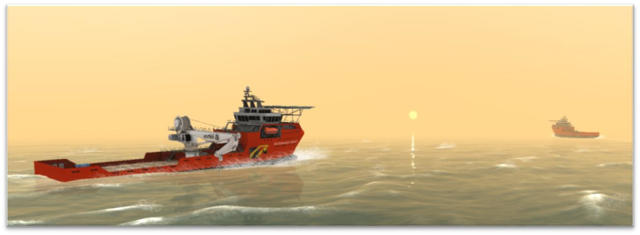
This scene features an offshore scenario to demonstrate the use of Vortex Studio in a marine environment. It includes a controllable knuckle boom crane mounted on a vessel to transfer equipment from the vessel to the seabed.
Highlights
- This scene illustrates how Vortex Studio can be used to perform lift planning and validation in an offshore environment.
- The ocean simulation includes wave modeling, water surface reflections, and propeller effects. It is possible to change the waves' size and the wind force during the simulation.
- The Vortex Studio Human library is used for all avatars present in the scene, including the slingers and supervisor.
- The Hooking of equipment is controlled via Python scripting.
- Vessel operations can be simulated using crew avatars on the vessel deck (the signaler role is controllable with a gamepad to walk around the ship).
- All components of the scene use the multi-texturing feature. o Texture masks allow the ships' windows to reflect light differently than the hull o The equipment has a "used" appearance, with scratches and dents
- The moving support vessel uses scripting to combine particle effects with the Buoy extension to create a bow wave/splash.
- The environment uses the Skydome and Ocean features to add detailed cloud layers as well as wind streaks on the water surface.
- The crane operator position has a Viewpoint set for multiple-display use.
Operation Notes
- Use the crane control to hoist up the subsea module and land it on the vessel deck.
- Unhook the subsea module using the gamepad.
- During the simulation, a script can control the motion of the knuckle-boom crane drum to compensate for the heave motion of the vessel.
- Select the Signaler Role to walk around the vessel deck in the first-person view using the gamepad controller.
Simulation Notes
- The scene includes two intervention vessels with equipment on deck, a Floating Production Storage and Offloading (FPSO) ship, and a subsea module (EDP) hooked to a knuckle-boom crane.
- The observation intervention vessel is used to illustrate the bow wave and thruster wash effects.
The former automatically move in wide circles around the scene.
- Ocean properties are defined in the Ocean Dynamics extension under the Environment Properties. By changing the inputs and parameters of this extension in the Vortex Studio Editor, it is possible to alter the sea state and sea current.
- Under the Ocean Dynamics, the Ocean Graphics extension can be used to tune ocean visibility (fog, silt) and ocean reflection/color.
- Environment controls (such as the time of the day and weather conditions) can be changed under Environment/SkyDome.
- You can also change the shape and properties of the cloud cover via the Custom Cloud extension. Python Scripts
- Underwater Visibility Control lets the user toggle between topside and subsea visibility levels directly from the gamepad.
- Inline Help manages the display of the gamepad control diagram in the lower-left corner of the screen.
- Propeller Speed returns a propeller speed based on the vessel's own speed. This is used to set the propeller wash effect.
- Crane Controller takes inputs from the VHL (and thus gamepad) and combines them to drive the boom and stick, acting on the constraint linking the crane together. The signals are processed via a low-pass filter to give a similar feeling to real hydraulics.
Offshore Sea Bed – Subsea Field with ROV
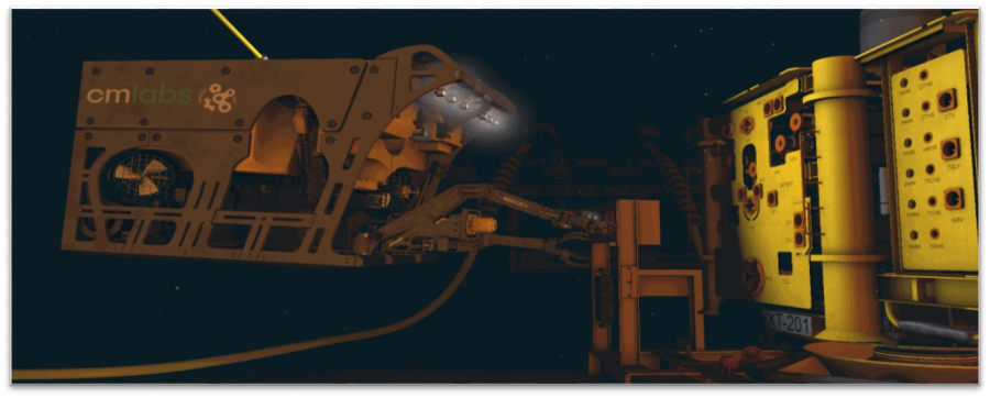
This scene provides an offshore scenario to demonstrate the use of Vortex Studio in a marine environment. It includes a Remotely Operated Vehicle (ROV) with robotic manipulators and tooling to perform subsea interventions.
Highlights
- Vortex Marine is used to simulating the hydrodynamics of an underwater vehicle (ROV).
- This scene showcases the three types of cables available in Vortex Studio:
- Generic Cable: flexible cables used to model the tether cable connecting the ROV to the Tether Management System (TMS) and to model the umbilical connecting the TMS to the LARS system on the offshore vessel.
- Catenary: used to model the flexible risers connecting the FPSO to the subsea modules on the seabed.
- Pipeline: used to model fixed pipelines on the seabed.
- The scene is also a good example of modeling and control of robotic manipulators using joint-by-joint control or inverse kinematics using Python scripting.
- Ocean modeling including sea current and underwater visibility.
- ROV features an automatic station-keeping feature to facilitate the use of the arms.
- A configuration allows the simulation to generate silt in the water if the ROV comes close to the sandy seabed.
- All components of the scene use the multi-texturing feature. o The sub-sea terrain has a natural look with no tiling visible up close o The equipment has a "worn out" appearance, with scratches and dents
- The sub-sea terrain is a Graphics Gallery, which allows the use of multi-texturing.
Operation Notes
- Before launching the simulation, you can select whether the ROV will carry arms or not via a scene configuration.
- When piloting the ROV, make sure you spool out enough tether to properly operate the remote vehicle.
- Different cameras can be used to monitor ROV interventions:
- Docking Camera: the docking camera is used to assist the ROV operator during the latching of the ROV into the TMS.
- ROV Camera: camera located in front of the ROV during normal ROV interventions. Allows the operator to navigate the ROV and perform manipulations using the robotic manipulators on the ROV.
- Titan4 Camera: this camera is installed on the wrist of the Titan4 robotic manipulator. It can be used for better visibility when grasping objects.
- Third-Person View Camera: this is a camera to monitor ROV operations from an observer point of view. You can control the view of this camera by clicking on the left mouse button and using the mouse to position the camera.
- Use the gamepad buttons to toggle between the ROV and the robotic manipulators. If the ROV Operator role is active, the HUD/image in the down-right corner of the screen will highlight which equipment is currently being controlled.
- You can toggle between clear or realistic underwater visibility.
- This scene also illustrates how simulation can be used to perform subsea accessibility studies.
The torque tool installed on the ROV can only be partly inserted into the AAV Bucket on the
Christmas Tree due to contact between the top of the ROV and the top of the Christmas Tree (see picture below). Using the Vortex Studio Editor, the torque tool can be repositioned lower on the ROV in order to be able to fully insert it into the AAV bucket.
Simulation Notes
- Ocean properties are defined in the Ocean Dynamics extension under the Environment Properties. By changing the inputs and parameters of this extension in the Vortex Studio Editor, you will be able to alter the sea state and sea current. Under Ocean Dynamics, you will also find the Ocean Graphics extension which can be used to tune ocean visibility (fog, silt) and ocean reflection/color.
- Control of the ROV thrusters is achieved using seven thrusters extensions located in the ROV mechanism (see below).
- The arms are equipped with cable grabbing and cutting extensions – activate the Configurations as needed. You will need to manually match the extensions' contact material with a cable, in order to grab or cut the latter.
Python Scripts
- ROV Multiple Device Selection lets the user toggle between the various controls and tools attached to the ROV.
- ROV Controller checks the desired ROV velocity coming from the gamepad and computes the required thruster speeds necessary to create that motion. It then outputs the control signals to the thruster extensions.
- Thruster Joystick Command checks the signals coming from the gamepad and computes a direction signal to feed to the ROV Controller script.
- Camera Controller checks the joystick inputs for the camera and turns them into a tilt velocity for the constraint that attaches the camera to the ROV.
- Torque Tool Display checks the number of rotations made by the tool and converts them into the text to be displayed.
- Titan4 Joystick Mapping takes the various joystick inputs and converts them into velocities suitable for use by the Inverse Kinematic script.
- IK – Titan4 takes the current and desired positions of the arm, and computes the required joint motions required to complete the command.
- Rig Master Joystick Mapping takes the various joystick inputs and converts them into velocities suitable for use by the Inverse Kinematic script.
- TMS Drum Control takes the gamepad input and converts it into an angular velocity for the drum constraint. It also imposes a limit to that speed via a set parameter.
Excavator and Dump Truck
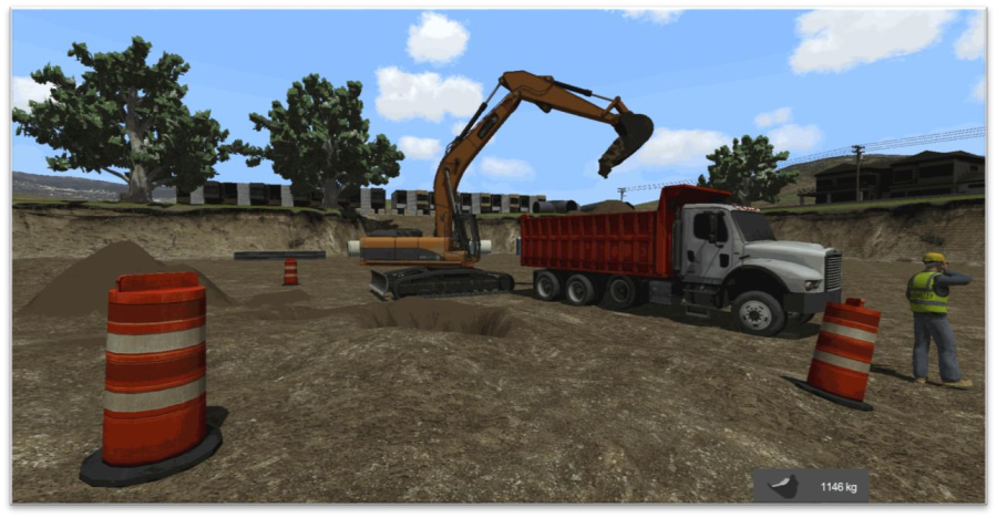
This scene provides a digging scenario on loam soil with a 36-ton excavator and a three-axle construction truck vehicle. The excavator features both a bucket and a dozing blade to move soil around with. The truck combines a Vehicle Systems model with simple logic to drive it; in addition, it provides a control for both brake and retarder combined. Highlights
- The excavator mechanism provides a hydrostatic Vehicle Systems model with rigid tracks. The logic provides hydraulic controls for all actuators with a low pass filter to simulate inertia.
- The entire area between the orange cones can be dug into, including the loose soil pile to the left. Soil can be excavated using the bucket or pushed with the dozer blade. Excavated soil can be dumped in the truck or added to the pile. The SSM soil graphic feature is enabled.
- The Vortex Studio Human library is used for all avatars present in the scene, including the operator and supervisor.
- The trees and other vegetation come from the Vortex Studio Vegetation library. Via a configuration, a concrete pipe can be buried in front of the starting position of the excavator. It cannot be dug out of the ground, but it can be uncovered and re-buried.
- All components of the scene use the multi-texturing feature.
- The terrain is a Graphics Gallery.
- Both the excavator operator and truck driver positions have a Viewpoint for multiple display use.
Operation Notes
- The Excavator comes with two control modes, digging or driving.
- To dig with the excavator, use the controls to operate the turret and the hydraulic actuators of the boom and arm.
- To drive the excavator, switch to Drive mode, and use coordinated left and right track commands to move forward, backward, or turn. The excavator can pivot in place.
- The excavator's dozer blade can be lowered or raised in either mode.
- The truck can be driven and its bed emptied.
- The excavator can use either a standard or a narrow bucket. Activate the associated mechanical configuration to equip the desired one.
Simulation Notes
- Scene configurations include several different starting points and options for the simulation.
- Boom and arm have some relaxation in their constraints to provide torsion under heavy forces. The visuals of the dug soil use the Screen Space Mesh (SSM) feature. This fills the space between soil particles and helps create the illusion of loose earth.
- The Soil Layer tool, combined with empty collision geometries, is used to generate the loose soil pile. Adjusting the Relative Density field will change the pile's shape as it settles. The starting shape can also be modified by changing the collision geometries in the Soil Pile mechanism.
- The Soil Layer tool is also used to create the buried concrete pipe (it is set to 'non dig-able'). Note that the collision geometry of the latter is slightly smaller than the graphic to ensure good visual interaction with the soil flowing around it.
- A VHL interface is used to change the bucket soil material configuration from the scene to avoid changing the mechanism file for each soil type. In the Player, this is accessed via the Content Debugger tab: open the Content folder, then the Scene folder, then the Excavator folder, and locate the Earthwork Bucket entry. A simple Cable system is used to model the flexible sections of the excavator's hydraulic lines. The forces of the lines are prevented from affecting the parts of the vehicle. They are attached in order to optimize the simulation.
- The Mirror extension is used to create a reflective surface in the cab's left-side mirror. Since the right-side mirror cannot be seen without changing the point of view, it has been left bare to improve performance.
- The glass windows of the cab have a slightly colored, yet transparent (Alpha) graphic material with Reflections enabled.
- The truck model features soft soil tire models tuned for loam and mud operations.
Python Scripts
- Actuator Controller takes inputs from the VHL and joystick and uses them to drive the arm, acting on the constraint linking the arm's hydraulic cylinders. The signal is processed via a lowpass filter to give a similar feeling to real hydraulics.
- Engine Controller controls the state of the engine, and whether the excavator is in digging or driving mode.
- Mode Dispatcher takes the command signals and sends them to the proper destination, depending on the operating mode currently selected (digging or driving).
- Sound Controller checks the current status of the excavator and plays the associated sounds from a set series of .wav files.
- Inline Help manages the display of the joystick control diagram in the lower-left corner of the screen.
- Bucket Controller animates the truck bed when it moves up and down.
- Gear Value returns the exact gear mode and number for the VHL output interface.
- Truck Controller is the main control scrip of the vehicle. It handles the gear (Park, Gear Up, and Down) and engine state of the dump truck. It takes various inputs (either from the VHL or other scripts), and returns values to the Vehicle Systems and constraints to get the truck in motion. This script also mixes the brake and retarder values so the driver does not have to bother with controlling them separately.
- Differentials Controller turns the differentials on the truck on or off. If desired, this script could easily be merged with the Truck Controller script, to reduce the total number of scripts running in the scene.
- HUD Controller manages the display of the speed, RPM, and current gear at the bottom right of the screen. Note that this script is placed at the scene level so it can be used by both the truck and the excavator.
Console Features
The console is a simulator feature available with Vortex Studio Activate
The excavator scene has been enhanced with Equipment and Exercise to showcase the console features. These two files enable the excavator, its configurations, and exercises to be displayed in the selected pages of the console. You can try the new features by using the provided vxsimulator files in the demo scene:
Run the Vortex Studio Director (a shortcut is available on your desktop)
From the Tools menu, open the Settings... submenu to select the location of the simulator files (/CM Labs/Vortex Studio Content (release name)/Demo Scenes/Resources/config/). All simulators will appear in the left panel of the Vortex Director.
Select the 01_Console_Operator simulator and Launch it. The simulation starts up with the Excavator equipment selected, along with the Standard bucket type. Load the Simple Practice exercise.
When the exercise is running, switch to the Operator Control page, which shows a realistic, interactive image of the cabin controls particular to the excavator. Press the Engine Start button to start the excavator, and rotate the throttle dial clockwise to increase the engine's power. Some buttons and switches also respond to mouse clicking but are not connected to the simulation. Please consult the console user guide available in the Vortex Studio documentation for more details. 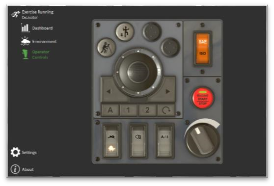
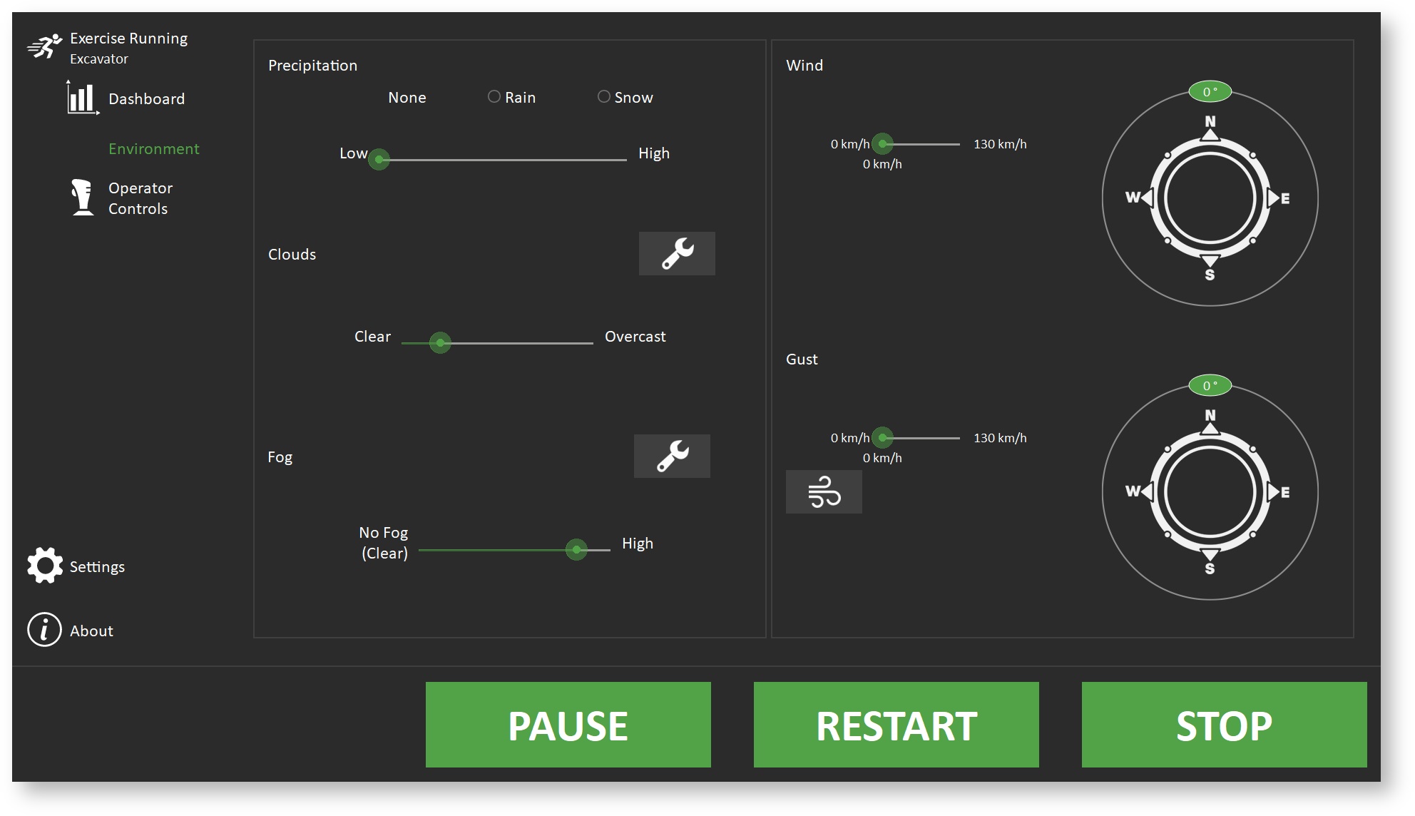
The 02_Console_Instructor simulator will display various user interfaces specifically designed for an instructor, where you can log into the database, select an exercise, define and display metrics for scoring computation as well as control the weather. Feel free to modify and re-use this sample to experiment with all the possibilities. 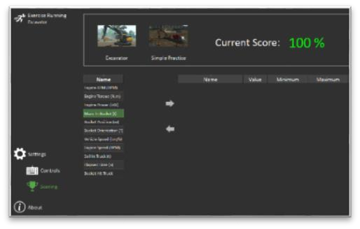
Packbot for Explosive Ordnance Disposal
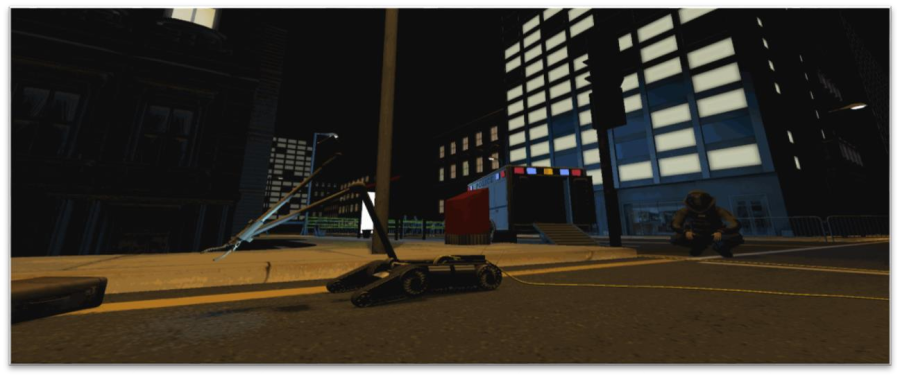
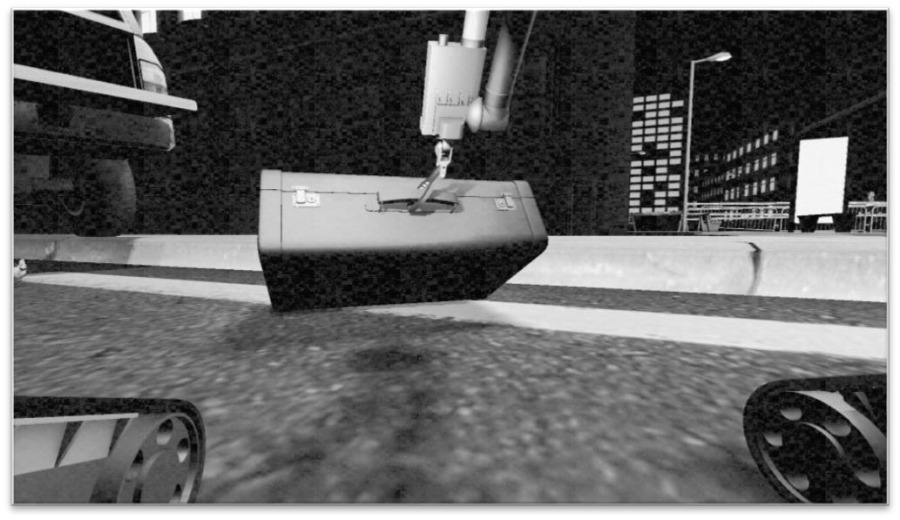
This scene provides a remotely-operated, tracked robot used for bomb disposal, reconnaissance, and surveillance. It is available as a tethered, wire-guided version and a wireless radio-controlled one. The Packbot can climb stairs, relay video from the mounted cameras, and grab small objects such as a suitcase, as demonstrated in this example. Highlights The gripper showcases Vortex Studio's grasping simulation capabilities. The inverse kinematics controls make it easy for untrained operators to control the arm: simply push the claw toward where you want it to go. The robot comes with two onboard cameras, one in the base and one at the top of the arm. They can be controlled in either mode. The lower one has a spotlight attached to perform an inspection in dark places (under the truck, for example).
- The optional optic-fiber control tether auto-spools out the back of the robot as it moves about. It can be paid out or reeled in manually if needed.
- The Vortex Studio Human library is used for all avatars present in the scene, including the robot operator, police officers, and crowd.
- All components of the scene use the multi-texturing feature.
- The scene is set at night to showcase emissive textures. Both the vehicles and the buildings have self-illuminated textures for windows and light sources.
Operation Notes
- The robot can be controlled using a gamepad with four directions. When using full left or right, it roughly turns on the spot (depending on flipper position).
- To operate with a tether, navigate to the Scene Configurations panel and activate the configuration for the tether.
Note that the tether automatically spools out when the Packbot moves, but this can be overridden with the gamepad's shoulder buttons.
- By selectively raising or lowering the flippers (forward tracks), the robot can cross obstacles such as stairs or curbs.
- When set to Gripper mode, the arm uses invert kinematics for control: the joysticks control the gripper's position in space and not the various joints of the arm.
- The robot's gripper can grab the suitcase's handle. Switch to Gripper Mode to access the controls for the gripper, wrist, and arm.
Simulation Notes
- The robot mechanism uses a Vehicle Systems with four tracks controlled by two electric motors for left and right propulsion. On each side, the tracks are connected together to a single motor using a shaft.
- The detailed collision geometries for the gripper's fingers were generated with the V-HACD convex decomposition feature, set to Intermediate.
- Two filters are connected to the camera to simulate the low-bandwidth and interference of the remote connection: noise and black & white.
- By default, the tether is not present (to model a radio-controlled robot). To add it to the scene, select the scene configuration called "Tethered Packbot.".
- The tether is an adaptive cable with greatly reduced stiffness. The openings of the box at the rear of the robot are modeled with two Cable Ring constraints.
- Emissive textures are included to illuminate the night scene in conjunction with numerous point lights. The street lamps use a lightmap instead of individual light sources to save on processing power. The map was generated by taking a screenshot of the scene viewed from the top and using a graphic program to paint the desired lighting. Python Scripts
- Warning Lights uses sin waves to provide oscillating values for the Intensity of the police truck's emergency lights.
- Arm Controller takes the various gamepad inputs and converts them into velocities suitable for use by the Inverse Kinematic script.
- Cameras Controller checks the gamepad inputs for the camera and turns them into a tilt velocity for the constraint that attaches the camera.
- Chassis Controller takes the flipper, direction, and speed signals and converts them into motions for the flippers' constraints, and engine values for the Vehicle Systems.
- Gripper Controller takes input signals for the gripper and wrist and converts them into motion via the gripper and wrist's motor constraints.
- Packbot Controller is the main dispatcher script for the Packbot. Input signals from the VHL and joystick are sent to the proper destination based on the operating mode (driving/gripper).
- Spooling Controller takes the joystick input and current chassis velocity and uses them to provide an angular velocity for the tether drum constraint. The script includes a built-in scaling factor ("ratio"), which could be extracted into a set parameter instead if desired.
- IK Controller takes the current and desired positions of the arm, and computes the required joint motions required to complete the command.
- Inline Help manages the display of the joystick control diagram in the lower-left corner of the screen.
Forklift in Warehouse
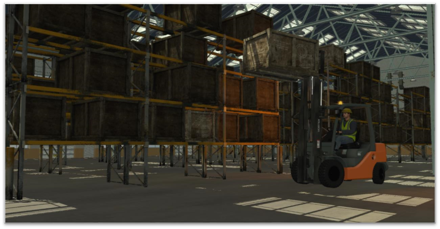
This scene provides a medium-duty forklift with pallets and boxes to move around in a warehouse.
Highlights
- The forklift is a basic mechanism built with parts and constraints.
Note: the model does not use Vehicle Systems or Hydraulics Systems.
- Cable Systems are used to model the lift chains on the forklift.
- The forklift is equipped with twin spotlights and a custom rotating warning light.
- The Vortex Studio Human library is used for the forklift driver.
- The ambient lighting is provided by multiple real-time light sources.
- Some boxes can be moved between racks. Movable boxes have a slightly different color.
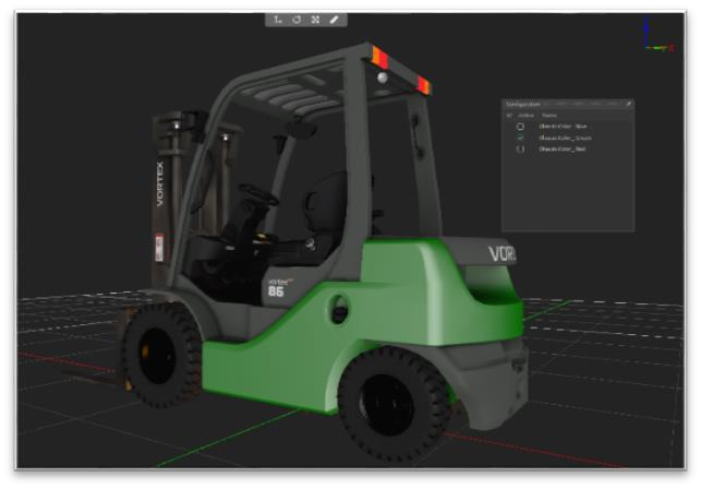
- All components of the scene use the multi-texturing feature. Change the forklift's color!
- The forklift driver position has a Viewpoint set for multiple display use.
Operation Notes
- The right stick both steers and sets the desired gear; accelerate/brake with the triggers.
- The rear wheels are powered and steerable; this gives the forklift a very tight turning radius. Both front wheels are free.
- The steering wheel and speed lever models follow the motion of the vehicle, providing additional visual feedback to the operator.
- It is possible to tilt the driver's viewpoint with the D-Pad to help to place boxes on shelves.
- The carriage can be extended up and down, tilted forward and back, and the forks shifted left and right. Note that the mast can go quite high – keep an eye on the ceiling.
Simulation Notes
- The Scene Configuration feature includes different starting points for the simulation.
- You can change the color of the vehicle's body by selecting one of the mechanical configurations in the forklift mechanism.
- The warehouse is a Mechanism in itself, with the Assembly set to Static.
o Note that no Terrain object is used in this scene.
- For improved performance and frame rate, not all racks and boxes can be interacted with.
- Multiple light sources cast real-time shadows across the scene.
- A basic Skybox is used to provide a sky backdrop to the windows.
- The rotating warning light uses multiple transparent planes and a custom script to recreate the halo effect. It is set to not cast shadows to save on processing power; if a powerful computer is used, shadows could be enabled for a more realistic appearance.
- A Vortex Studio Human driver figure is placed within the cab. The Human Dynamic and Human Control elements have been removed since they are not needed: the driver figure is completely enclosed within the cabin's collision geometry. Python Scripts
- Forklift Controller takes various input signals from the VHL interface (which is itself connected to the Joystick extension), and applies a low-pass filter to simulate the hydraulics. The signals are then outputted to the various constraints to make the forklift respond to the controls. It is possible to adjust the reaction time by changing values within the script.
- Revolving Light Controller puts together two spotlights and creates a rotation animation for them. The resulting position data is also used to drive the graphic nodes of the rotating light and the simulated light halos attached to it.
- Camera Controller changes the orientation of the driver's viewpoint based on the D-Pad inputs.
- Linear Speed Calculator is used for the HUD display.
Engineering Test Terrain
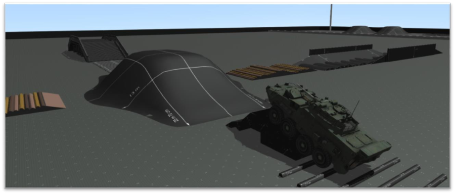
The Engineering Test Terrain asset provides an environment where vehicles and mechanisms can be tested under different operating conditions. There are various modules and obstacles to interact with.
Highlights
- Modules provide several obstacles to test vehicle crossing capabilities.
- Changing the material of the ground allows different types of driving surfaces (e.g. sand, ice, snow) to be simulated to test vehicle slipping and road holding.
- All components of the scene use the multi-texturing feature.
Operation Notes
- The engineering test terrain is intended as a configurable environment. Simply select, copy, and move props around in Vortex Editor as needed to create a customized path.
- Different materials can be set for the ground or modules to test traction.
- The LAV from the Defense Vehicles scene is included to quickly begin testing.
Simulation Notes
- The props are created as Mechanisms to allow them to be moved around; if they were part of the Terrain, they would not be selectable.
- All props are set as Static to improve simulation performance.
- The new Scene Configuration feature includes several different starting points for the simulation.
Python Scripts
- None are used in this scene.
Sports Car Scene
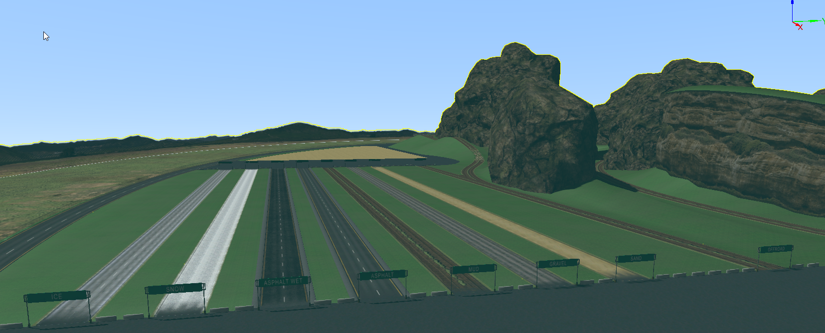
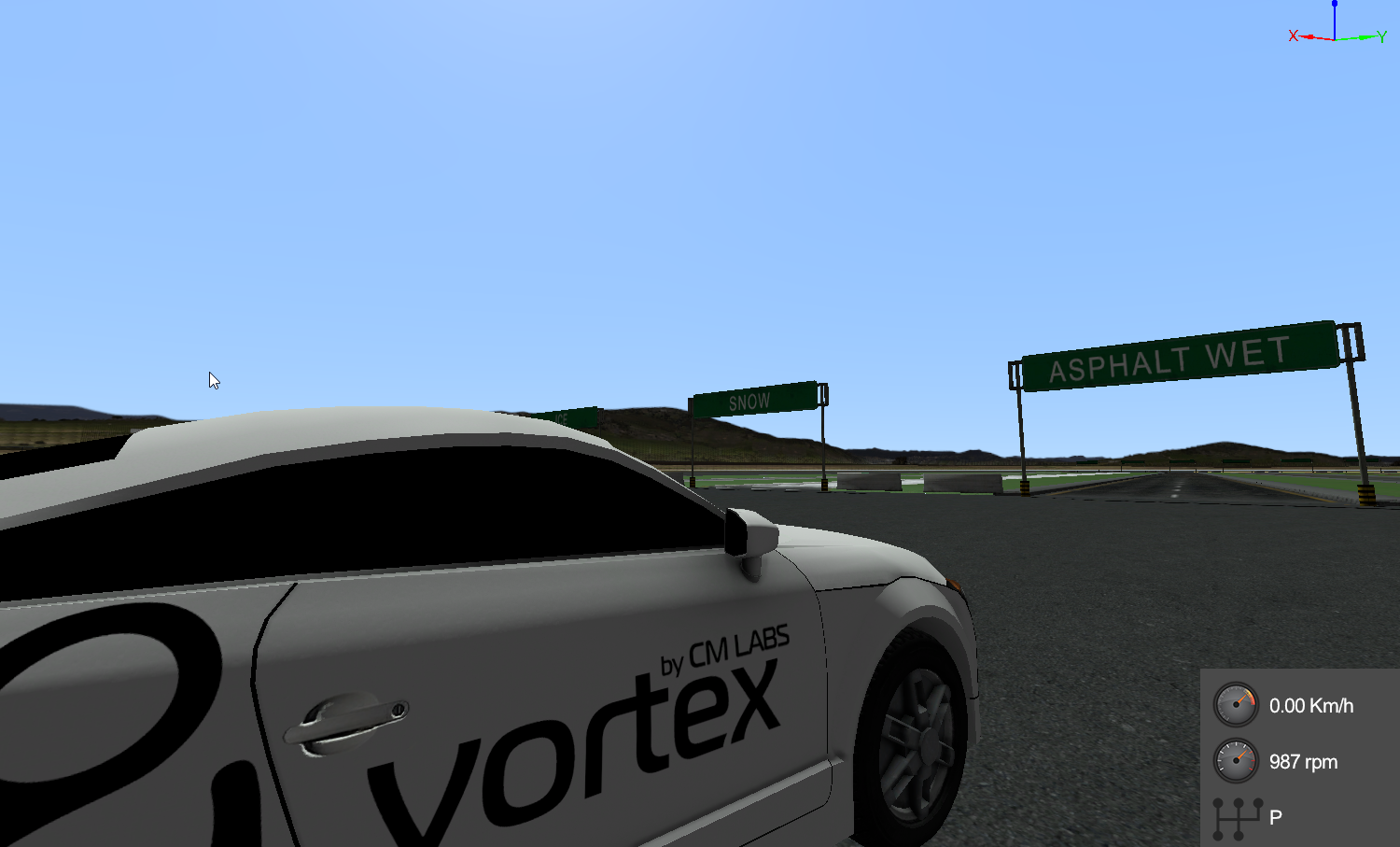
The SPORTS CAR SCENE provides an environment where vehicles and mechanisms can be tested under different road conditions. There are various modules and obstacles to interact with.
Highlights
- Sandpit practice
- Sand road
- Gravel
- Mud
- Asphalt/Wet Asphalt
- Snow
- Ice
- obstacles (rocks, bumps.....)
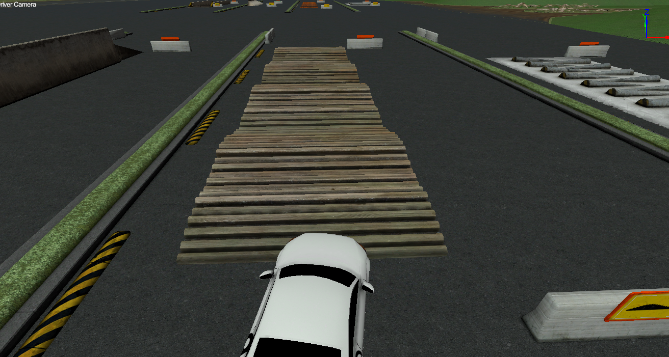
Operation
- Forward Drive D1/D8
- Reverse Drive R1/R6
- Park and Neutral
- Steering, Throttle, and Brake
Materials Gallery
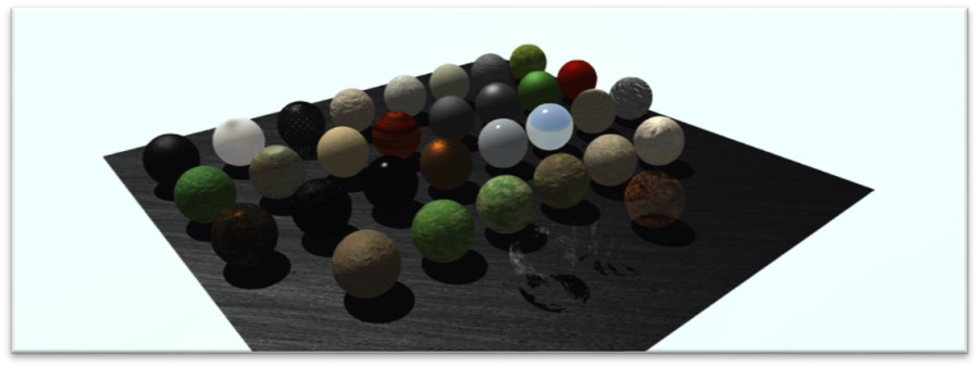
The Materials Gallery provides a number of pre-set, non-PBR (Physics-Based Rendering) graphics materials that can be used in your own models or as a visual reference. It is a Graphics gallery and can be modified, copied, and pasted in the Vortex Studio Editor.
The various Materials here have been designed with seamless textures, which is important to create useful modular material. You can use this scene as is; you could also import new textures and add your own new materials to it, to grow your own Material Library.
Metals
Metal Copper (1024x1024): this is a copper-like material that provides a good example of how to set a graphics material for metal if not using PBR. Note the values for Specular and Gloss channels.
Metal Black Flat: this is an example of metal that was painted with a mat black finish.
Metal Undulate Rusted (4098x4098): this is a high-detail rusted metal, with a normal map to provide the undulations required to simulate a corrugated metal sheet without having to create 3D geometry.
Metal Rust (2048x2048): this is a common rusted surface. It could be used for old or damaged vehicles, walls, or anything that has been left in the elements.
Metal Grey Flat: this is a metal painted with a flat gray primer.
Chrome: this is a non-PBR, chrome-like material. To provide the required reflections, make sure "Environment Reflections" is turned on and add a Sky Box to your scene. The latter will need to have colors similar to your scene's environment (for example, the bottom side should be colored like the ground).
Plastics
Plastic Red (1024x1024): this is a plastic-like material that provides a good example of how to set a graphics material for plastics. Note the values for Specular and Gloss channels.
Plastic Abrasive Green (1024x1024): this material uses a Normal map to create the bumps and ridges.
PVC Matte: this material emulates PVC plastic.
PVC Soft Matte: this material emulates another type of PVC plastic. It's a good base to start new plastic materials from.
Woods
Wood Honey (1024x1024): this is an example of how the various textures and channels can be used to create very rich-looking materials, in this case, a varnished wood.
Wood Plywood (2048x2048): this is standard plywood, of the kind used on construction sites everywhere. Use it to create walls, boxes, pallets, etc.
Wood Dirty (4098x4098): this is an old wood structure that has been left out in the elements a while. The green paint has faded to a greenish-blue and started to peel from the surface.
Nature
Foliage (1024x1024): this is a basic material for the foliage of trees and shrubs.
Grass (2048x2048): this is a basic material for grass-covered areas.
Construction
Brick (1024x1024): this material is used to emulate bricks. Its color can be adjusted to match whatever is required for the scene.
Ground
Concrete (1024x1024): use this material for anything made out of common concrete.
Gravel (2048x2048): this material uses a Normal map to provide the illusion that it's composed of multiple small rocks rather than a single image.
Mud (4098x4098): use this material for mud-like surfaces, such as freshly-dug earth, a construction site after the rain, or a wetland.
Mud (1024x1024): this is another mud-like material, though using a lower-resolution texture to occupy less memory space.
Sand (1024x1024): this is a basic material for sand and dust-covered areas.
Rock (1024x1024): this is a basic material for rocks and rocky areas.
Miscellaneous
Chicken Wire Fence (2048x2048): this is a specialized example of what can be done with graphics materials. Here, the texture with a wiring pattern has an alpha channel. The Blend mode is set so that it appears transparent. Using this material on a wall will emulate a fence that can be seen through but not moved through.
Metal Frosted (1024x1024): this material is another uncommon use, this time playing with the Specular and Gloss channels to give the illusion of a frosted-over piece of metal.
Graphite, Charcoal (1024x1024): this is a carbon-like material that can be used for graphite or burnt area, depending on how it is set with masks.
Particles
The following materials are intended to be used for particles. They are set on a transparent (alpha) backdrop.
SnowFall particle: this material is used to create snow. It can also be added as a layer to the top of existing models to simulate a thin, freshly fallen snow cover.
Rain particle: this material is used to create water droplets. Use it in a particle emitter if your scene requires rain, but you do not want to include a Skydome extension.
Silt particle: this material was intended to simulate underwater silt, but it can also be used for other dust-like material.
Multi-Textured
The following materials were built using multiple textures and mask layers. They provide examples as what can be done using the latest Graphics Gallery features, but can also be used "as is" in your own scenes. All materials use 1024x1024, lower-resolution textures to occupy less memory space. Using reduced-size texture is essential in the optimization process of your scene's performance.
Foliage Multi: use this for a foliage mix, or to create richer vegetation.
Foliage Mud: use this for mixed ground cover.
Foliage Mud Gravel: use this for a complex ground cover that includes various soil types as well as some vegetation (grass or freshly cut plants).
Gravel Mud Var01: this is a rough mix of gravel and mud. Useful for construction sites.
Gravel Mud (1): this is another variation of the previous material.
Sand Rock: this is a mixture of sand and small rocks, perfect for desert-like environments.
Textures
The graphics materials were created using the textures found in this folder. Most of the textures are seamless to allow them to be applied easily on any surface with a UV set.
The file names follow the recommended conventions, consisting of a label for identification, the type of texture (albedo, normal, etc.), and its resolution (512, 1K, 2K, etc.).