Cable Systems
- DEVOPS
 The Cable Systems extensions allow you to use the Vortex Studio Editor to create a cable system definition in which a series of point definitions you specify and attach to existing parts make up its segment definitions.Cable systems hoist, lift, and drop items. To do this, they need to be made up of a few different components: winches, pulleys, rings, segments, two endpoints, and zero or more midpoints. Segments, which can be fixed, variable, or flexible, are made up of sections.
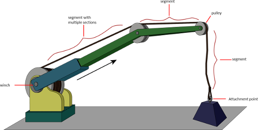
Cable System Components
The following are the components that make up cable system.
The graphics here are used to illustrate the concepts and may not reflect the make-up of your cable system.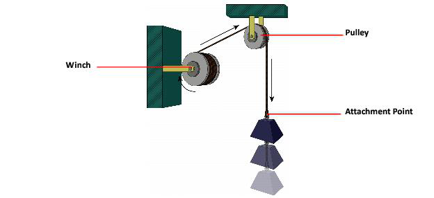
Points
The winch and the attachment point are known as endpoints, while the pulley, or a ring if included, are known as a midpoint. A cable system cannot contain more than two endpoints, however, it can have as many midpoints as it allows. As shown in the following illustration, the section of the cable between two points is known as a segment.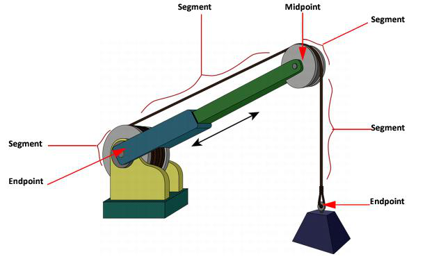
Segments
There are three types of segments as shown in the illustration below: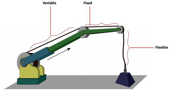
Variable length segment
The length of the cable can increase or decrease. For example, the length of the last segment shown in the illustration above can vary depending on the lowering of the load.
An arc is usually of variable length as an attachment point on the pulley will change to keep the segment tangent.
Flexible segment
The shape can changed depending on tautness. Thus if the cable is slack, as shown, it will be more relaxed.
Fixed length segment
The length of the cable will not change as the two parts do not move with respect to each other.
Note If you are certain that the segment should be of fixed length, make sure that you set the proper parameters. You can change a segment of variable or fixed length to flexible length. To simulate real life scenarios, Vortex® offers parameters that can allow cable segments to collide with objects in the simulation environment. It is also possible to simulate cable breakage at a specified segment location.
Designing Cable Systems
Cables don't exist until runtime, when Vortex® reads all definitions and generates dynamics to interact with other mechanisms in the scene, as well as the graphics in order to provide visual feedback to the operator.
For this reason, conceptualizing how the whole system works before defining anything is strongly recommended.
Before you can create a cable system, you first need to create the mechanisms on which it is to be attached, which you can easily do in the Vortex Studio Editor. These mechanisms include:
- Winch
- Pulley
- Rings
- Attachment Points
These items represent a series of points through which Vortex draws the cable lines (wires, chains, etc.) in a straight line from point to point. So the trick is to figure out where you need each point to go so that the segments (straight lines) connecting them will create a realistic cable system definition.
Points
At least two end points must always be defined: one to attach the load to be hoisted; and another to attach the cable to the mechanism which is hoisting the load (for example, a winch on a crane). Typically, several mid points are also defined and each time a new point is added, Vortex recalculates the cable information such that the cable is drawn in a realistic position.
The end points can be either attachment points (where the cable is attached to a mechanism) or winches. Mid points can be either pulleys or rings. Points are directly associated to Dynamics parts.
Segments
Vortex adds segments automatically every time you add a point:
- End points always have a full segment on only one side of the point; on the other side you might have an arc segment if your end point is a winch.
- Mid points always have full segments on both sides.
Note The key to building a cable system is in defining it.
Building Cable Systems
When you are designing a cable through the Editor or the SDK, you start by creating a cable system definition container, adding a set of parameter definitions in its own container where you define and customize a number of point and segment definitions.
SDK
- CableSystems uses the Dynamics ICD in order to interact with Vortex® Dynamics. In this way, it sends pertinent information to Dynamics to calculate the physics behind the cable systems. It takes all updated positional change information it receives from Dynamics and sends it through a graphics ICD for its visualization.
- See Cable Systems Interface Control Document (ICD) for information on how to interface with CableSystems.
- The CableSystemDefinitionContainerID contains such information as where the cable passes in the simulation, the properties used by physics, and its position at load time.
- The CableSystemParamDefinitionContainerID consists of several parameters: the radius, density, maximum tension allowed before the cable breaks, the number of frames before the tension causes the cable to break, whether the cable is breakable, the name of the material from which the cable is made.
- The CableSystemDefinitionContainerID consists of other definitions as well, primarily that of PointDefinitionContainerID . Attachment, end, and middle points are all PointDefinition objects that make up the CableSystemDefinition. It is the PointDefinition object that indicates where the cable is going to pass; its middle point indicates where the cable touches the part. In essence, it is the points that define the cable system.
Editor
The Cable Systems provides Dynamics and Graphics components for your cable which use the SDK under the hood but allows you to define a cable system by configuring parameters at three different levels:
Cable Systems Types
The Cable Systems is a way to create cable systems in your simulations.
A generic dynamic cable in Vortex® is the most configurable and simple cable. Using the pipeline and catenary cables allows you to efficiently create specific types of cables for different applications (e.g., subsea applications). Each cable can be customized similar to a regular cable to fit the particular simulation.
The pipeline and catenary cable system allows the customization of specialized cable operations that is configurable with the ability to simulate complex cables with collision detection.
Generic Cables
Catenary Cables
Pipeline Cables
Adaptive Cables
Sub-Topics
The following topics are covered in this section: