Modifying Segment Definitions
- DEVOPS
Each segment definition allows you to customize how that segment will behave in the simulation.
| A segment is automatically created as soon as you define at least two points (winch, pulley, etc.) and appears in the Dynamics property page under the Parameters > Segment Definitions section. |
At runtime, Vortex® reads all definitions and generates dynamics for each segment. The Collision Geometry Type drop-down list allows you to select the geometry shape to use when generating the dynamics for this segment.
The segment's Collision Geometry Type defines the collision geometry for the current segment except if you select Undefined, in which case the segment's Collision Geometry type will be the one from the Param Definition.
If you select None in the Segment Definition, the segment will have no collision geometry even if, for example, the Param Definition's Collision Geometry Type is set to Capsule. If you select the capsule, then the collision geometry will be a capsule for this segment even if the Collision Geometry Type of the Param Definition is set to something else.
To avoid collisions between the attachment point's part and the cable, an internal collision rule was created between the part and the cable, thus removing all possibilities of collision. This internal collision rule can be overridden by a user's collision rule if collisions are desired between the attachment collision part and the cable.
Care must be taken to avoid having a segment inside the collision geometry of the attachment part at start and at runtime when the cable can be spooling in at high speed. The offset of the attachment point can be used to place the extremity of the cable outside the collision geometry of the part.
Other parameters you can modify include:
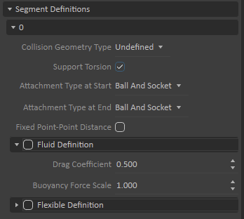
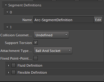
- If you want this segment to have a fixed length (for example, between two pulleys), enable the Fixed Point-Point Distance parameter. This is an optimization so the distance between the two Point Definitions must be constant or the behavior of this segment will be undefined.
- Enable the Flexible parameter to make this segment flexible (for example, so it can appear as slack cable. You can customize how this segment initially appears when the simulation starts.
If this segment is sitting in water, enable the Interacting With Fluid parameter to produce realistic fluid effects. You may also need to adjust the Buoyancy Force Scale (ratio of volume between the collision geometry and the real object) and Drag Coefficient parameters.
To have any interaction with the fluid, the segment must have a collision geometry.- Support Torsion, which indicates whether the segment supports torsion and springs back to a torsion-free position
Creating Flexible Segments
This procedure explains how to make a cable segment flexible and customize how this segment initially appears when the simulation starts.
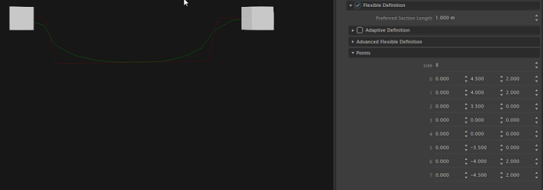
| When flexible segments are slack, they usually hang or fall in a smooth curve in the real world. In order to achieve the proper initial position in a simulation, you can define a Cubic B-Spline curve that represents the path of the slack segment by creating several control points. |

Under the Parameters>Definition>Segment Definition section in the Dynamics property page, enable the Flexible parameter.
The Fixed Point-Point Distance will be unchecked if the flexible segment is selected since both are incompatible.
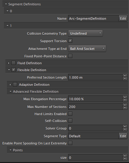
Rigid Cable Flexible Cable You can set the Preferred Section Length to create the number of sections of the segment (piecewise elements creating a flexible segment).
Note As you decrease this value, the shape fidelity of the segment will increase at the expense of simulation time but this can be overcome by setting the segment to Adaptive.
You can specify a different set of limits for the number of sections for this segment by modifying the Max Number of Sections parameter values.
Set the value of the size parameter under the Points section to match the number of points you need to define a custom shape (Cubic B-Spline curve) for the slack segment when the simulation starts.
As you change the size value, you can see new sets of numeric parameters representing each XYZ coordinate. Each of these coordinates represents a point along the Cubic B-Spline curve defined in world space.
It is possible to set the number of control points to 0. In this case a straight line will be created between the two point definitions.Enter new coordinate values for each control point to adjust the line of your curve. As you edit these values, the 3D View displays the spheres in the new locations and also provides a green indicator to represent the Cubic B-Spline curve while you define it.