Catenary Cables
A catenary cable are cable where segments of the cable shape follow a curve, or catenary shape, because of a force field such as gravity, buoyancy field, or current flow. The shape and number of segment of the catenary cables can be defined in the editor parameters. The catenary can have the following shapes defined:
- Lazy wave
- Free Hanging
- Steep Wave
- U Shape
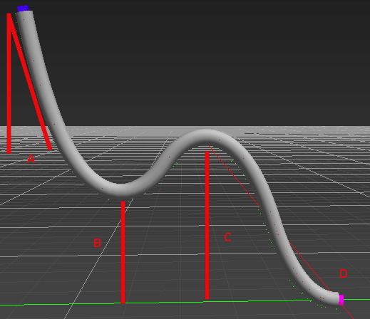
A Lazy wave contains a catenary, followed by an inverted catenary, and finally another catenary.
The global shape is set such as to be continuous of the second order.
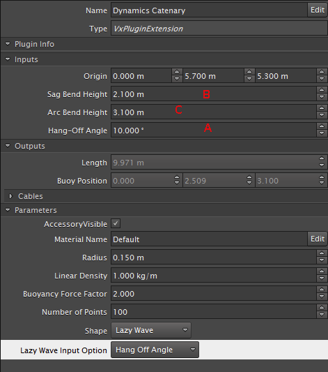
You can adjust the lazy wave shape by the Hang-Off Angle (A) or End Point depending on the selected Lazy Wave Input Option. Selecting End Point in the Lazy Wave Input Option allows you to specify the end point of the wave. Selecting the Hang-Off Angle allows you to specify the input angle. You can also configure the sag bend (B), and arc bend (C) height to create the desired cable definition.
|
| 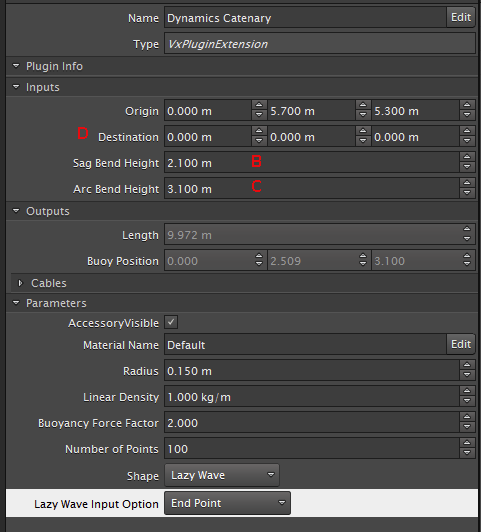 |
The Lazy wave catenary can be modified using the following parameters:
- Sag Bend height: The distance between a plane passing by the destination point and its normal parallel to the force field direction and the minimum point of the first segment.
- Arc Bend Height: The distance between the plane (see above) and the maximum point of the second segment.
- Hang- Off Angle: The angle between the force field and the direction of the cable at the origin.
A Free hanging catenary cable contains one to three segments:
- A straight segment passing by the origin in the direction of the force field.
- A second segment, half the shape of the catenary, with the minimum point at the bottom catenary.
- A final straight segment passing by the destination point perpendicular to the force field.
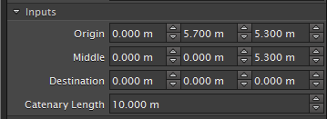
You can configure the length of the free hanging catenary cable to find the best shape by using the origin and destination inputs. The total length of the cable must also be close to the input Catenary Length value.
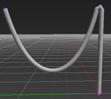
The U shape catenary occurs if the input Catenary Length is bigger than the distance between the origin and the destination (total length).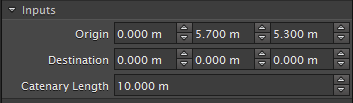
The Steep wave catenary contains two segments. The first segment is a catenary with the input Catenary Length bigger than the distance between the origin and the middle point. The second segment is a straight line between the middle point and the destination point. The number of points -1 is distributed equally on the first segment.
|
|
Creating Catenary Cables
Using the cable system you can create long cables, or many cables specifically to subsea simulation applications.
The Vortex® catenary cables were created to mimic cables used to move fluids or gas to or from the seabed. Catenary cables can also be used for a variety of specialized cable simulations.
To add a catenary cable:
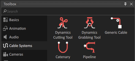
In the Toolbox, click Cable Systems.
Select Catenary and drag it into the 3D view or to the mechanism in the Explorer panel.
To view the dynamic parameters of the catenary, select Dynamics Catenary in the Explorer panel.
In the Properties view, under parameters, click the Shape drop-down menu to select the shape of the catenary.
Depending on the shape of the catenary, additional parameters can be adjusted in the Properties view. The shape of the catenary can be changed and further customized in the Input section of the properties page.