Sensors
In order to add a sensor to your content in the editor:
- Select Sensors in the Toolbox.
- Double-click the desired sensor to add it to the 3D View.
- Edit the name of the sensor in its Properties panel.
The following sensor extensions are available:
Distance Sensors
Geometry Distance Sensor
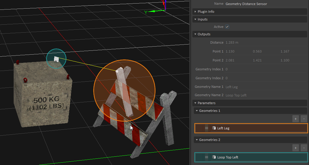
A Geometry Distance sensor measures the closest distance between specified collision geometries in your scene or mechanism. The sensor compares each geometry specified in the Geometries 1 group to each geometry in the Geometries 2 group, and returns the distance between the two closest geometries.
In the Properties panel, configure the following fields:
- Active: Select this box to compute the distance between the closest collision geometry in the Geometries 1 group to the nearest collision geometry in Geometries 2. Deactivating this input stops any distance measurements, and will reset the distance information outputs.
- Geometries 1 and Geometries 2:
- Size: Adjust this field to specify how many collision geometries you want to include in each grouping of geometries. Use the Browse button at the end of each row to bring up a dialog box where you can select a geometry from the Explorer panel.
Once you have specified all the collision geometries in both groups, press the play button in the editor to run the simulation, and consult the following outputs:
- Distance: Displays the minimum distance (in meters) between the geometry in the Geometries 1 group nearest to the closest geometry in Geometries 2.
- Point 1: The position of the point on the collision geometry from Geometries 1 nearest to the closest geometry from Geometries 2.
- Point 2: The position of the point on the collision geometry from Geometries 2 nearest to the closest geometry from Geometries 1.
- Geometry Index 1: Indicates the row in Geometries 1 that contains the geometry nearest to the closest geometry from Geometries 2.
- Geometry Index 2: Indicates the row in Geometries 2 that contains the geometry nearest to the closest geometry from Geometries 1.
- Geometry Name 1: Displays the name of the collision geometry referred to in Geometry Index 1.
- Geometry Name 2: Displays the name of the collision geometry referred to in Geometry Index 2.
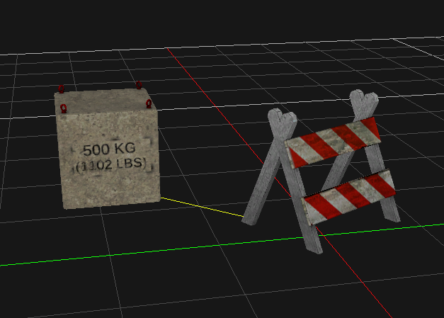
Optionally, you can display a visual aid in the 3D View that draws a line connecting the two collision geometries at their closest points (see image below). To do this, right-click the eye icon next to the Geometry Distance sensor in the Explorer panel, and enable Accessory.
Part Distance Sensor
A Part Distance sensor measures the closest distance between specified Parts in your scene or mechanism.
In the Properties panel, configure the following fields:
- Active: Select this box to compute the distance between Part 1 and Part 2. Deactivating this input stops any distance measurements, and will reset the distance information outputs.
- Part 1: Use the Browse button at the end of this field to bring up a dialog box where you can select the first part from the Explorer panel.
- Part 2: Use the Browse button at the end of this field to bring up a dialog box where you can select the second part from the Explorer panel.
Once you have specified the two parts, press the Play button to run the simulation, and consult the following outputs:
- Distance: Displays the distance (in meters) between the collision geometry within Part 1 closest to the nearest collision geometry within Part 2. If a part does not contain any collision geometries, the part's origins are used.
- Point 1: The position of the point on the collision geometry from Part 1 closest to Part 2.
- Point 2: The position of the point on the collision geometry from Part 2 closest to Part 1.
- Geometry Name 1: Displays the name of the collision geometry from Part 1 closest to Part 2.
- Geometry Name 2: Displays the name of the collision geometry from Part 2 closest to Part 1.
Optionally, you can display a visual aid in the 3D View that draws a line connecting the two parts at their closest points (see image below). To do this, right-click the eye icon next to the Part Distance sensor in the Explorer panel, and enable Accessory.
Overlap Sensors
Two sensors that detect overlaps are related. These are the Intersection Sensor, which detects overlaps of pairs of geometries, and the Raycast Sensor, which detects overlaps of geometries with a specified ray. These sensors can be used in conjunction with Sensor Triggers in order to detect such overlaps. In this context, a "sensor" triggers a "sensor trigger". The following section describes these concepts in more details.
Intersection Sensor
An Intersection sensor detects when a designated sensor trigger object collides (overlaps) with a collision geometry used as a sensor. A single sensor can contain multiple objects.
In the Properties panel, configure the following fields:
- Active: Check this box to toggle whether the sensor is in effect.
- Select Intersecting with Everything to have this sensor report intersections with everything. Leave this field deselected to have it report intersections only with objects labeled by a sensor trigger.
- Labels: Adjust the Size field to specify the number of labels given to this sensor. In the available slots, add custom text. Matching these labels to the same labels in a sensor trigger creates an interface between the two where you can control which sensor/trigger combinations result in a positive "Has Intersected" result in the sensor's output when contact is made.
Leaving a label blank acts as a wild card, matching this sensor with all labeled triggers, regardless of the triggers' labels. - Sensor Extensions: Adjust the Size field to specify the amount of objects whose interactions you want to associate to this sensor. After adding the appropriate number of extension fields, press the ellipsis button at the end of the row, then browse to and select the object you want to link to this sensor.
For example, if you wanted to detect when a car is in contact with the ground, you could add an Intersection sensor and add each wheel as a sensor extension. In the corresponding sensor trigger, you would add the terrain as a trigger extension. Finally, you would add matching labels to both the sensor and the trigger. When at least one of the four tires is in contact with the ground, the "Has Intersected" output would become true, meaning contact is made.
Raycast Sensor
A Raycast sensor detects when a designated trigger object comes into contact with an imaginary line segment of a user-defined length. Unlike the Intersection sensor, the Raycast sensor is placed at a user-defined point in space. If you want to tie the sensor to an object, you can use the Connection Editor to link its transform to those of another object.
- Max Distance: Specifies the maximum distance ahead of the sensor beyond which an intersection is no longer detected.
- Active: Check this box to toggle whether the trigger is in effect.
- Select Casting Ray on Everything to have this ray report intersections with everything. Leave this field deselected to have it report intersections only with objects labeled by a sensor trigger.
Labels: Adjust the Size field to specify the number of labels given to this trigger. In the available slots, add custom labels. Matching these labels with the same labels you added a sensor trigger creates an interface between the two where can control which sensor/triggers combinations result in a positive "Has Intersected" result in the sensor's Properties panel's output.
Geometries contained within Composite Geometries can be added to this list, but the corresponding entries will be disregarded.
For example, if you wanted to add a proximity sensor to a car to detect when it comes too close to pedestrian, you could add a Raycast sensor and, using the Connection Editor, link it to the car, pointing it ahead. Next, you would set the maximum distance past which proximity to a pedestrian is no longer a concern. In the corresponding sensor trigger, you would add the pedestrians in your scene as trigger extensions. Finally, you would add matching labels to both the sensor and the trigger. When a pedestrian comes within the range of the maximum distance, the "Has Intersected" output would become true.
Sensor Trigger
A sensor trigger detects when a designated sensor (Raycast Sensor or Intersection Sensor) intersects with it.
In the Properties panel, configure the following fields:
- Active: Check this box to toggle whether the trigger is in effect.
- Labels: Adjust the Size field to specify the number of labels given to this trigger. In the available slots, add custom labels. Matching these labels with the same labels you added in a sensor creates an interface between the two where you can control which sensor/triggers combinations result in a positive "Has Intersected" result in the sensor's Properties panel's output.
Trigger Extensions: Adjust the Size field to specify the amount of objects you want to set off a collision with the sensor. After adding the appropriate number of extension fields, press the ellipsis button at the end of the row, then browse to and select the object you want to link to this trigger.
Geometries contained within Composite Geometries can be added to this list, but the corresponding entries will be disregarded
Advanced: Creating Sensors and Triggers in Python Scripts
Raycast Sensors, Intersection Sensors and Sensor Triggers can be created directly in python. In this case, additional information can be obtained from the sensors, which is otherwise not available in the high level extensions. Among others, this includes detailed contact information such as contact positions and normals for every detected intersection.
The following example code snippets demonstrate how to create an Intersection Sensor paired with a Sensor Trigger in both Python 3 and Python 2 (legacy) scripts.
In both examples, the script requires the following parameters and outputs, which need to be added to the script manually in the editor.
Parameters:
| Name | Type | Description |
|---|---|---|
| TriggerExt | Extension Pointer | Represents the extension that will be used as sensor trigger. Can be any object that contains geometry, such as a Part, a Collision Geometry, or even a Cable or Vehicle. |
| SensorExt | Extension Pointer | Represents the extension that will be used as intersection sensor. Can be any object that contains geometry, such as a Part, a Collision Geometry, or even a Cable or Vehicle. |
Outputs:
| Name | Type | Description |
|---|---|---|
| Colliding | Boolean | Flag specifying whether a collision between TriggerExt and SensorExt (see above) was detected. |
| Contacts | Integer | Number of contacts found by the intersection sensor in every step. |
| Penetration | Double | Sum of penetration of all contacts that were found by the intersection sensor in every step. |
Python 3 example
from Vortex import *

def on_simulation_start(extension):
	extension.trigger = SensorTrigger()
	extension.trigger.setTriggerExtension(self.parameters.TriggerExt.value)
	extension.trigger.addLabel('Blue')
	extension.sensor = IntersectionSensor()
	extension.sensor.setSensorExtension(self.parameters.SensorExt.value)
	extension.sensor.setCollectingIntersections(True)
	extension.sensor.addLabel('Blue')

def on_simulation_stop(extension):
	extension.sensor = None
	extension.trigger = None

def post_step(extension):
	total_pen = 0
	total_con = 0
	for i in extension.sensor.getIntersections():
		total_con += len(i.contacts)
		for c in i.contacts:
			total_pen += c.penetration
	extension.outputs.Colliding.value = extension.sensor.hasIntersected()
	extension.outputs.Contacts.value = total_con
	extension.outputs.Penetration.value = total_pen
Python 2 example
from VxSim import *

def on_add_to_universe(self, universe):
	self.trigger = SensorTrigger(universe)
	self.trigger.setTriggerExtension(self.parameters.TriggerExt.value)
	self.trigger.addLabel('Blue')
	self.sensor = IntersectionSensor(universe)
	self.sensor.setSensorExtension(self.parameters.SensorExt.value)
	self.sensor.setCollectingIntersections(True)
	self.sensor.addLabel('Blue')

def on_remove_from_universe(self, universe):
	self.sensor = None
	self.trigger = None

def post_step(self):
	total_pen = 0
	total_con = 0
	for i in self.sensor.getIntersections():
		total_con += len(i.contacts)
		for c in i.contacts:
			total_pen += c.penetration
	self.outputs.Colliding.value = self.sensor.hasIntersected()
	self.outputs.Contacts.value = total_con
	self.outputs.Penetration.value = total_pen
Electro-optical Sensors
Vortex Studio comes with a set of electro-optical sensors which are described in detail below. Here is an overview of the output produced by the currently supported sensors.
| Lidar Sensor | |
|---|---|
| |
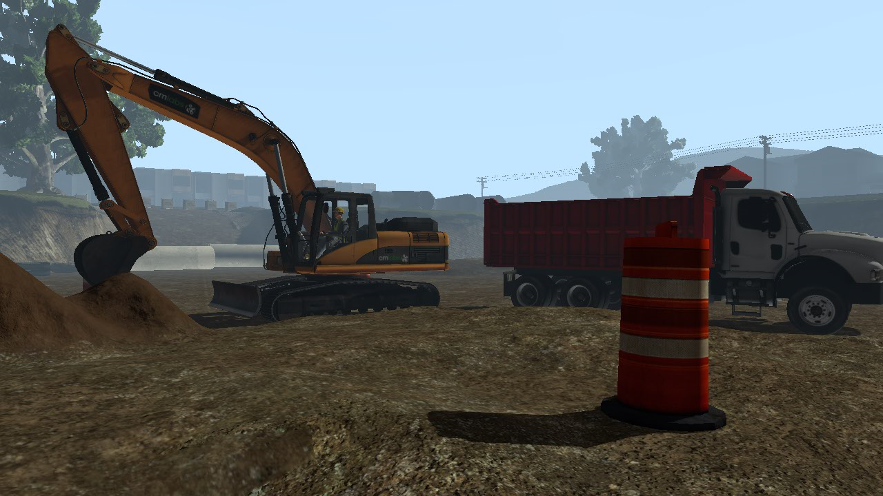
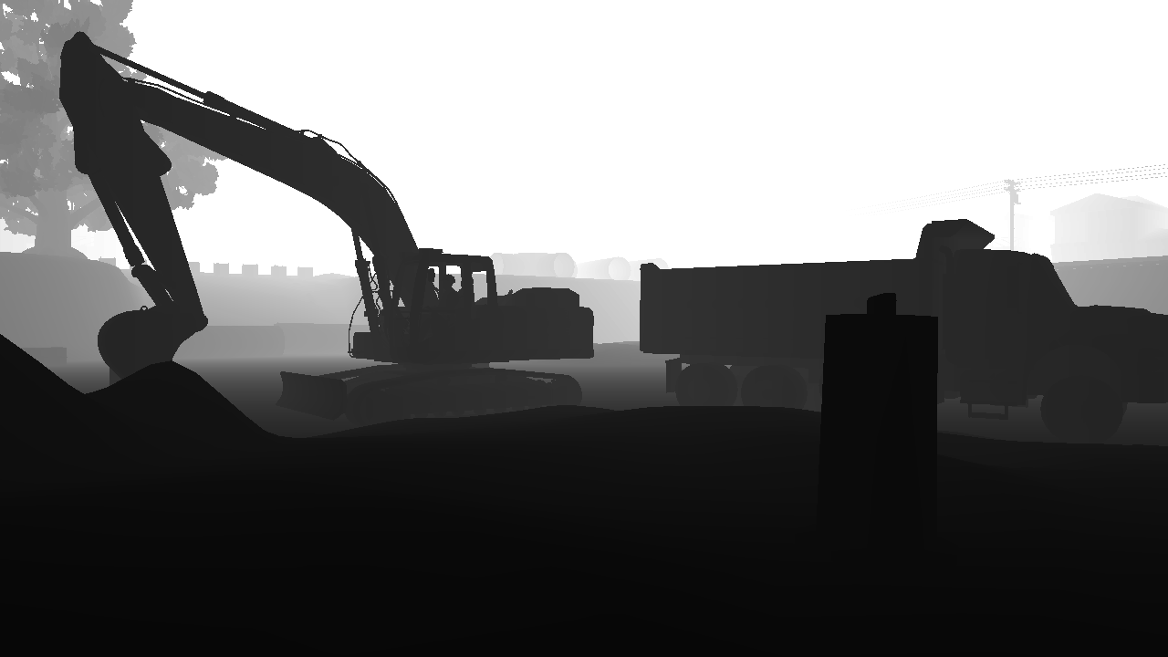
| RGB Camera | Depth Camera |
|
|
Lidar Sensor
The Lidar Sensor allows capturing a point cloud of the virtual environment in real-time. It can be placed in your scene or mechanism and attached to moving machines.
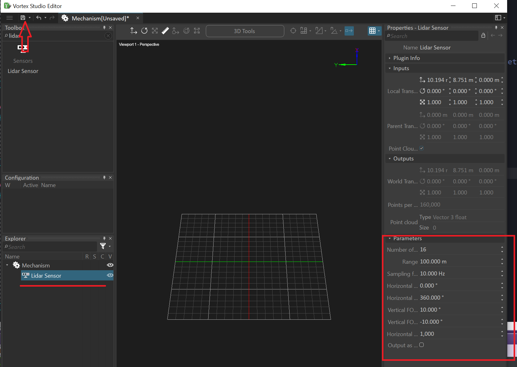
The Lidar Sensor provides a multitude of parameters which, among others, let you configure its sampling resolution and frequency among others. In the Properties panel, you can access the sensor's interface.
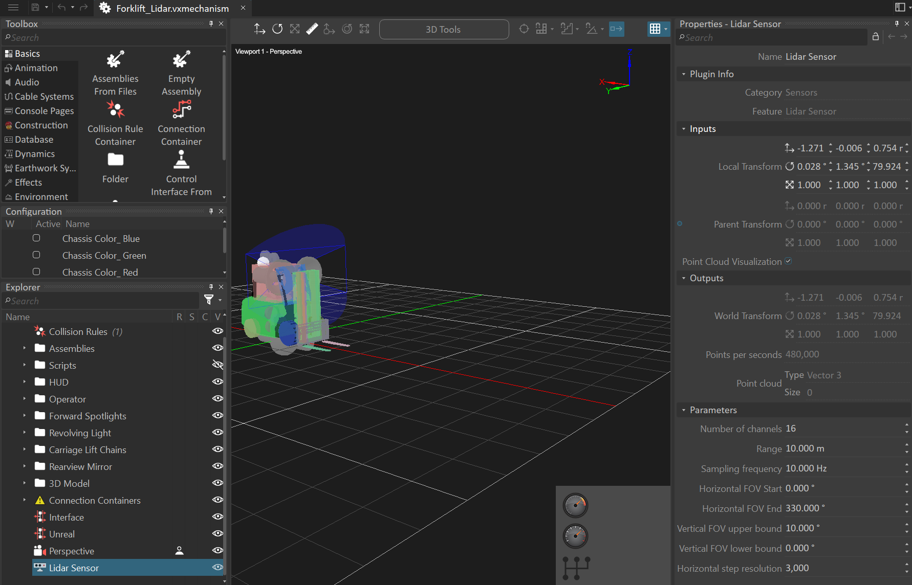
Parameters:
| Name | Description |
|---|---|
| Number of channels | Number of vertical stacks of lasers of the Lidar distributed uniformly across the vertical field of view (FOV). The valid value range for this parameter is 1 to 128. |
| Range | Range of the lasers of the Lidar in meters. The valid value range for this parameter is 1 to 10000 meters. |
| Sampling Frequency | Number of rotations (complete scans) per seconds of the Lidar. The valid value range for this parameter is 1 to 200. Note that setting the sampling frequency to a value greater than the simulation update frequency may result in loss of LiDAR data: |
| Horizontal FOV Start | The horizontal angle from the forward axis (x-axis) along the horizontal plane (xy-plane; formed by forward and side axis) at which sampling starts. |
| Horizontal FOV Length | The horizontal angular length of the laser scan. The end angle where sampling stops is equal to Horizontal FOV Start + this value. The valid value range is 0 to 360 degrees |
| Vertical FOV Upper Bound | The maximum vertical angle from the horizontal plane (xy-plane; formed by forward and side axis). The valid value range for this parameter is -180 to 180 degrees and the value must always be greater or equal to the value of Vertical FOV Lower Bound |
| Vertical FOV Lower Bound | The minimum vertical angle from the horizontal plane (xy-plane; formed by forward and side axis). The valid value range for this parameter is -180 to 180 degrees and the value must always be lesser or equal to the value of Vertical FOV Upper Bound. |
| Horizontal Step Resolution | The number of ray casts across the horizontal field of view (FOV) common to each channel. |
| Output as Distance Field | Set the output as a distance field if enabled or a point cloud otherwise. When enabled, the Distance Field output is filled, otherwise the Point Cloud output is filled |
Inputs:
| Name | Description |
|---|---|
| Parent Transform | Parent transformation matrix of the sensor. Connect the Parent Transform to the World Transform output of some other mobile object (e.g., a Part) in order to make the Lidar Sensor follow this parent object. |
| Local Transform | Local transformation matrix of the sensor. Use it to place the sensor relative to its parent object. The sensor follows the typical Vortex convention: X-forward, Y-left and Z-up. |
| Point cloud Visualization | Activate or deactivate the visualization of the generated point cloud during the simulation |
Outputs:
| Name | Description |
|---|---|
| Point cloud | The sampled data, provided as an output array of 3D points. Accessible, among others, via a Python script extension. Output Storage Convention The 3D point at index 0 of the output array is always mapped to the laser located at the bottom-left of the Lidar laser grid. Whilst the last 3D point contained in the output array is associated to the laser located at the top-right of the Lidar laser grid. The remaining of the data is stored in a column-major fashion. |
| Distance Field | The sampled data, provided as an output array of scalar values. The position of a laser in the lidar grid of lasers is directly associable to an index in the output array. The scalar value obtainable from the output array represents the distance traveled by the associated laser from the lidar to the hit location. The 3D point can be reconstructed from this index (which yield the laser ray cast direction vector by associativity) and the scalar value (the distance traveled along the vector obtained from the index). Output Storage Convention The scalar value at index 0 of the output array is always mapped to the laser located at the bottom-left of the Lidar laser grid. Whilst the last scalar value contained in the output array is associated to the laser located at the top-right of the Lidar laser grid. The remaining of the data is stored in a column-major fashion. |
Limitations
Please note the following limitations in the current state of the Lidar Sensor extension.
- No modeling of reflection intensity and generally any surface properties other than the geometry itself
- No modeling of noise or inaccuracies in the acquired data
- No multi-echo support, as in Hokuyo YVT-35LX
- No modeling of sine wave scanning patterns, as in Hokuyo YVT-35LX
Simulating specific Lidar Devices
Here is a list of example Lidar devices and the parameters to choose in the Lidar extension for their simulation.
Note that currently the Vortex Studio Lidar simulation does not model any advanced effects such as noise, reflection intensity or any other effects caused by material properties of the detected surface. So, the table below will only provide a way to obtain the sampling resolution and frequency of the respective Lidar devices.
| Devices | Parameters |
|---|---|
| Velodyne VLP 16 | Number of channels: 16 Range: 100.0 Sampling frequency: 5.0 Horizontal FOV start: 0.0 Horizontal FOV length: 360.0 Vertical FOV upper: 15.0 Vertical FOV lower: -15.0 Step Resolution: 3750 |
| SICK LD-MRS400102 HD | Number of channels: 4 Range: 300 Sampling frequency: 12.5-50 Horizontal FOV start: -42.5 Horizontal FOV length: 85.0 Vertical FOV upper: 3.2 Vertical FOV lower: 0.0 Step Resolution: 170-680 |
| SICK LD-MRS800001S01 | Number of channels: 8 Range: 300 Sampling frequency: 12.5-50 Horizontal FOV start: -42.5 Horizontal FOV length: 85.0 Vertical FOV upper: 4.2-6.4 Vertical FOV lower: 0.0 Step Resolution: 170-680 |
| Hokuyo URM-40LC-EW | Number of channels: 1 Range: 60.0 Sampling frequency: 40 Horizontal FOV start: -135.0 Horizontal FOV length: 270.0 Vertical FOV upper: 0.0 Vertical FOV lower: 0.0 Step Resolution: 1080 |
| Hokuyo YVT-35LX (No interlace mode) | Number of channels: 37 (approx.) Range: 35.0 Sampling frequency: 20 Horizontal FOV start: -105.0 Horizontal FOV length: 210.0 Vertical FOV upper: 35.0 Vertical FOV lower: -5.0 Step Resolution: 70 (approx.) |
Moving and Attaching the Lidar Sensor
By default, the Lidar Sensor is created at the origin of the world, but you can move it using the Transform toolbar or the transforms in its Properties panel.
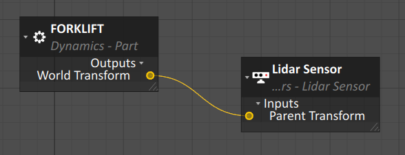
You can connect a Lidar Sensor to an object by linking the Parent Transform input of the Sensor extension to the World Transform output of the object using the Connection Editor.
Data Backends for the Lidar Sensor
We currently only support Lidar data gathering for Vortex Studio simulations built using the in-house Vortex Studio graphics engine or also those built for use in Unreal Engine with the Vortex Studio Plugin for Unreal. For more details on how you can use Unreal Engine to power your Vortex Studio simulation, you can read the available documentation.
Unreal Engine
No additional steps are required to setup the Lidar Sensor in Unreal Engine once it has been setup in your Vortex Studio mechanism. Simply add your Vortex Studio mechanism to an Unreal project and start the simulation. When the simulation starts, there is a small warm-up period (a couple of simulation steps) during which no data is produced. Afterwards, the Lidar will start gathering data from the 3D world that you built around it.
Unreal collision shapes are required for the Lidar to correctly detect and collide with static meshes (which are used in the Unreal Engine to represent both fixed and moving objects). For convenience, Unreal will automatically add complex collision shapes using the same mesh as the static mesh that was imported with an asset. Thus no further action is required to obtain functioning Lidar response. However, you may wish to reduce the complexity of the simulation scene by assigning simpler Unreal collision shapes to your static mesh in the Unreal Editor.
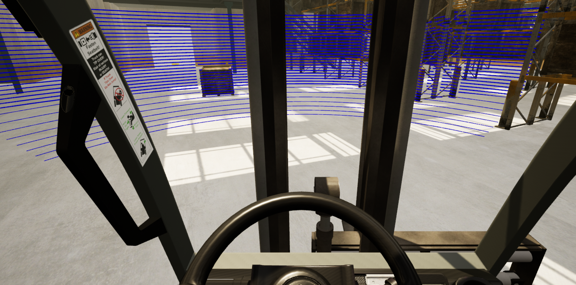
Below, we modified the free forklift sample project available on the Vortex Studio plugin page of the Unreal Engine Marketplace by adding a Lidar Sensor to the forklift mechanism.
For convenience, below you will find a step-by-step procedure explaining how to add a Mechanism containing a Lidar to Unreal and simulate.
- First, create a simple Mechanism containing a Lidar as follows.
- Start by creating a fresh empty Mechanism in the Vortex Editor.
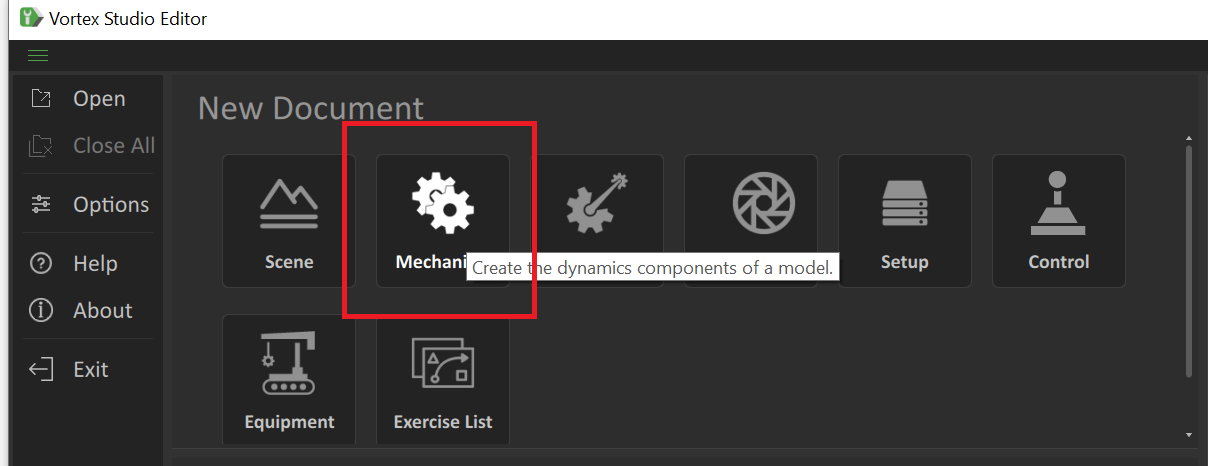
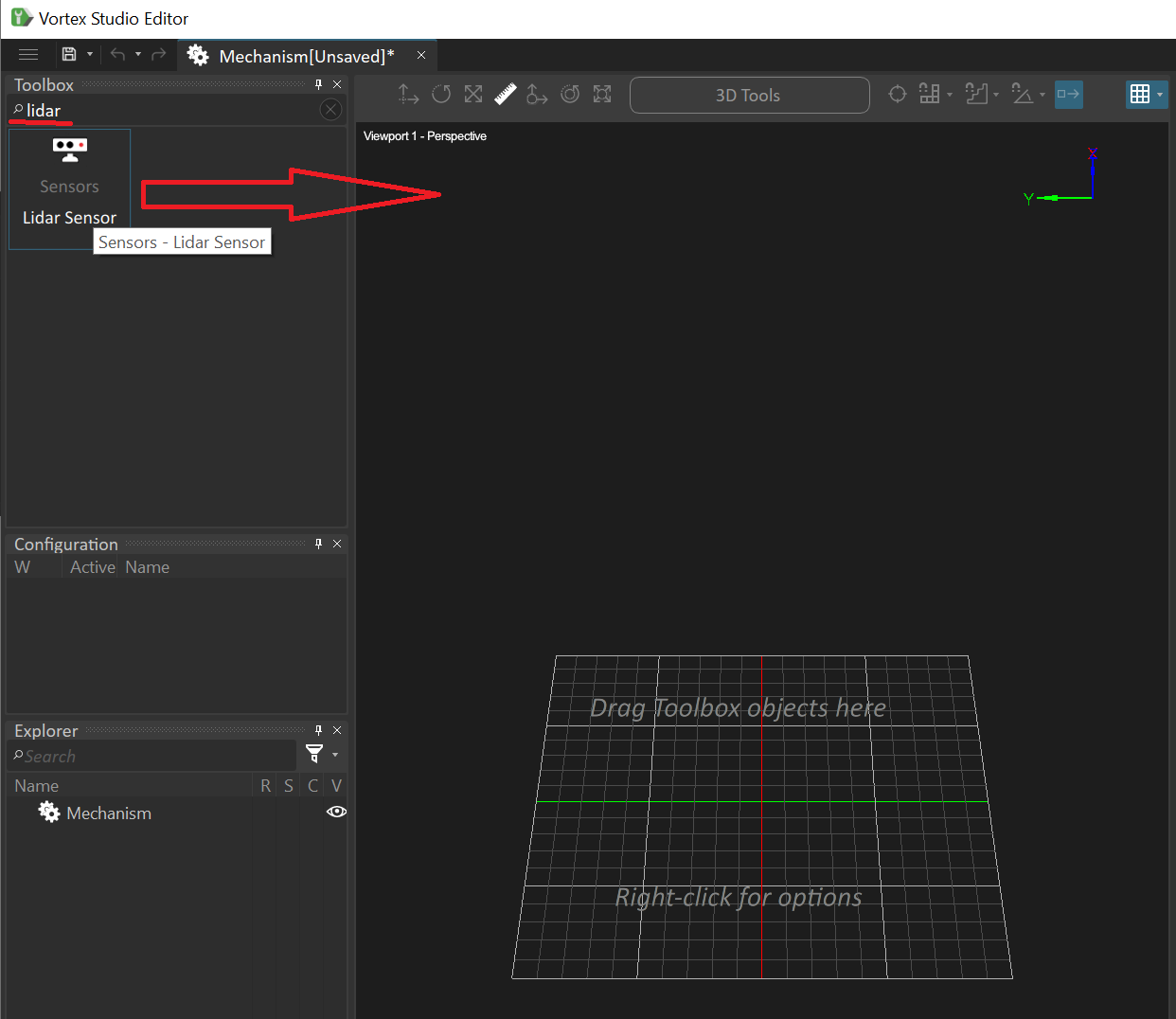
- Then search for Lidar in the toolbox and drag-and-drop the Lidar Sensor onto the viewport.
- Once added to the Mechanism change the Lidar parameters if desired, then hit Save and save to a location of your choice for now. When the Unreal project is created in the next step, or if you already have an Unreal project, we will move the Mechanism to the Content folder of the project.
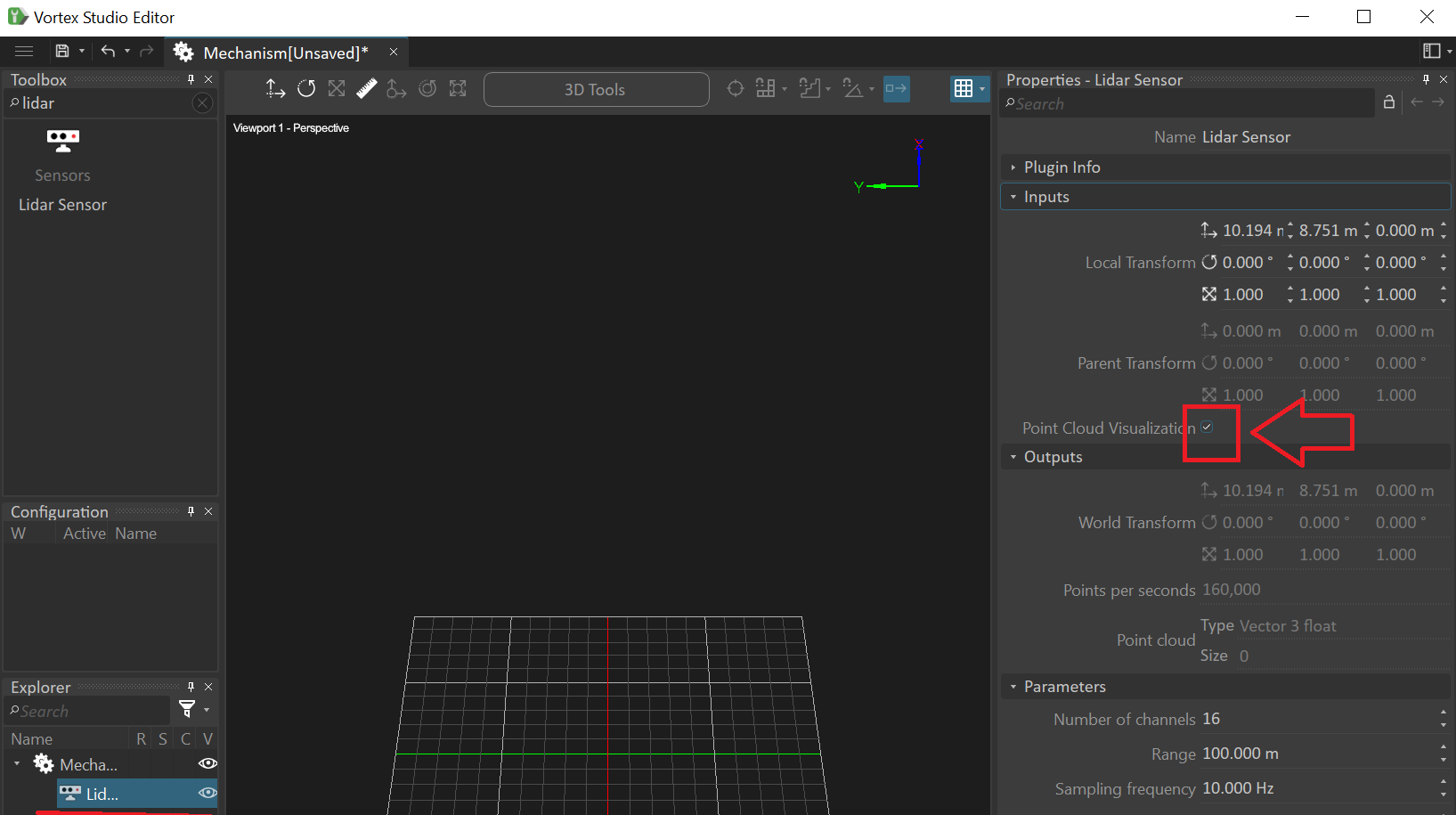
- Make sure the Point Cloud Visualization input is enabled
- Start by creating a fresh empty Mechanism in the Vortex Editor.
- Now, create a new Unreal Project:
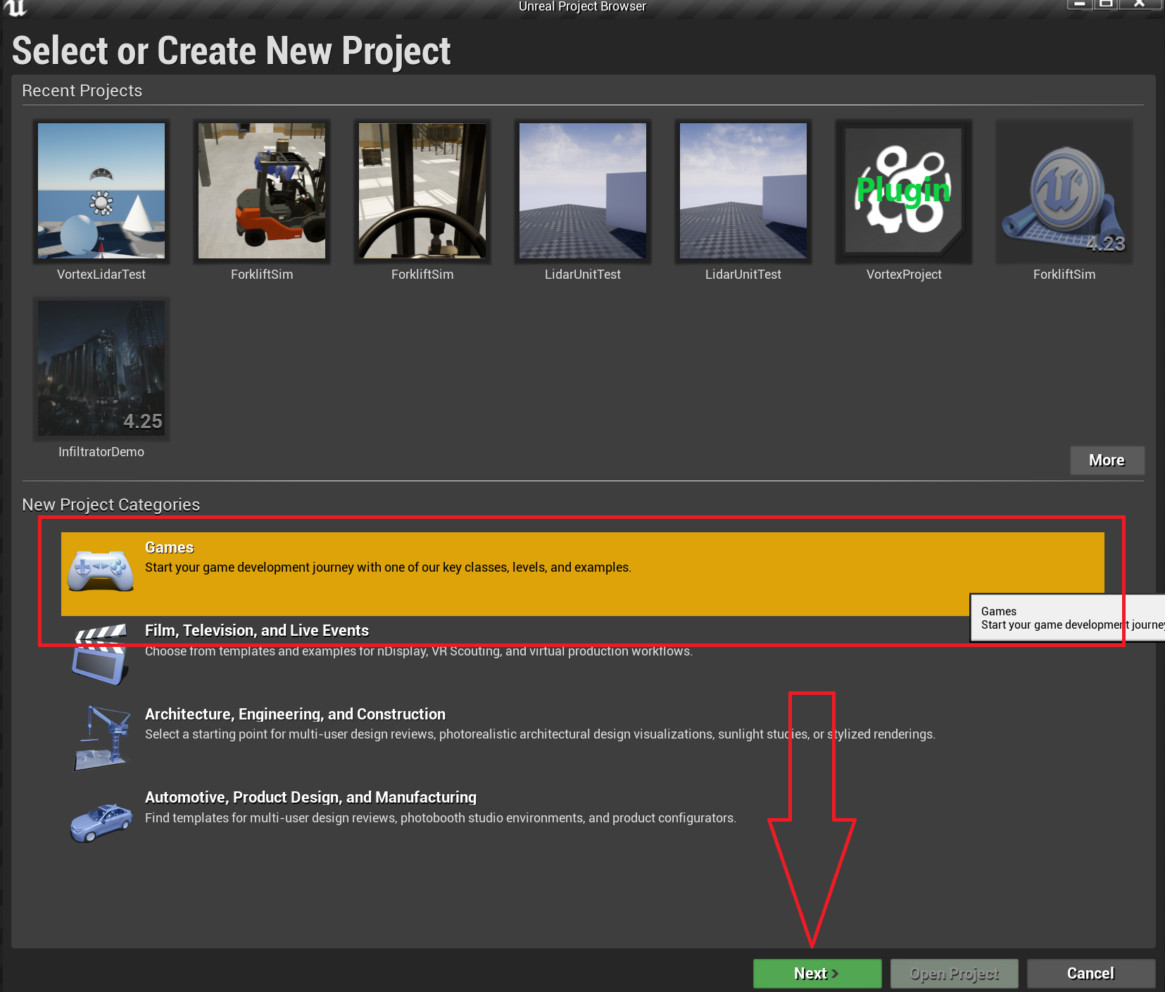
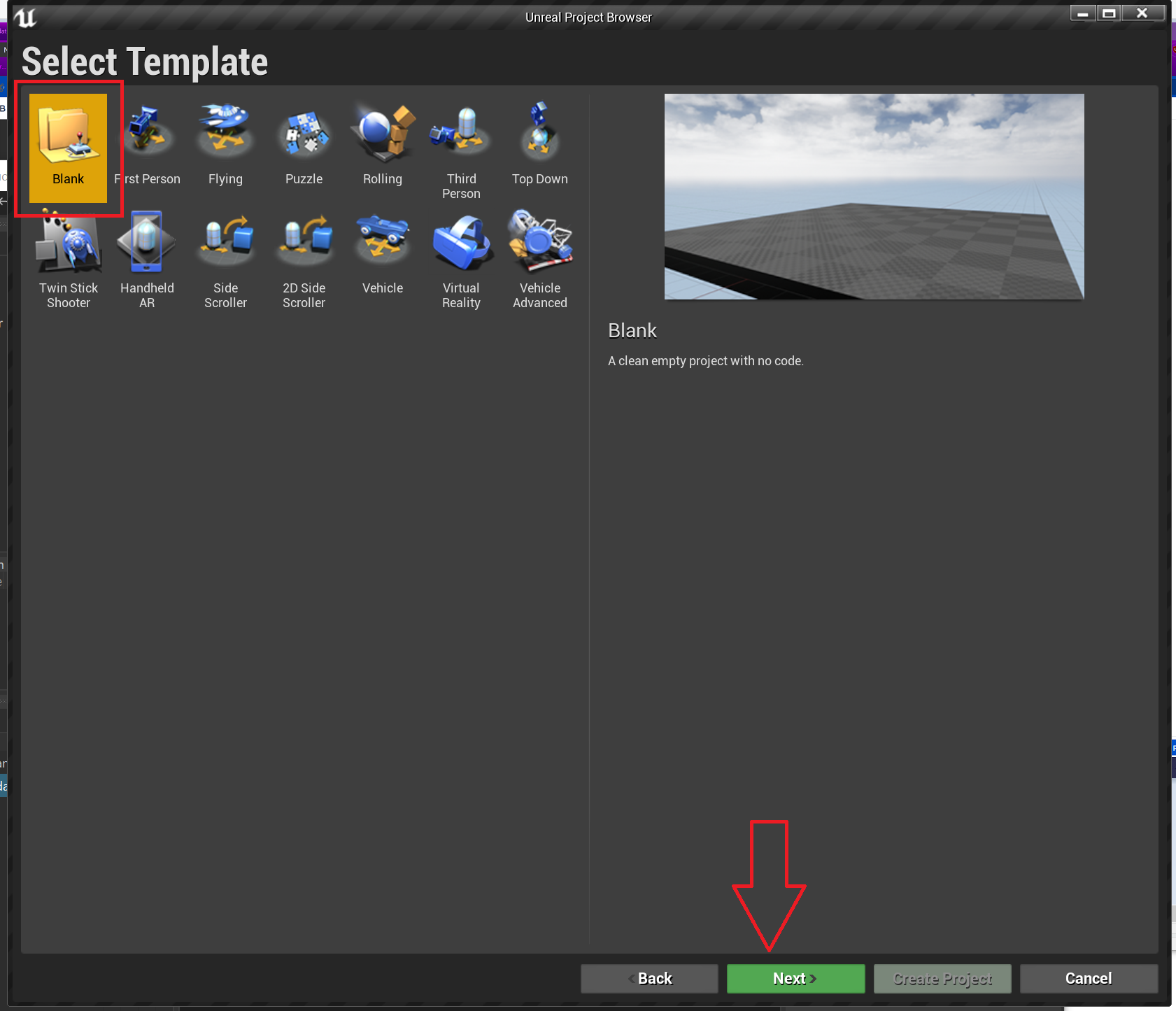
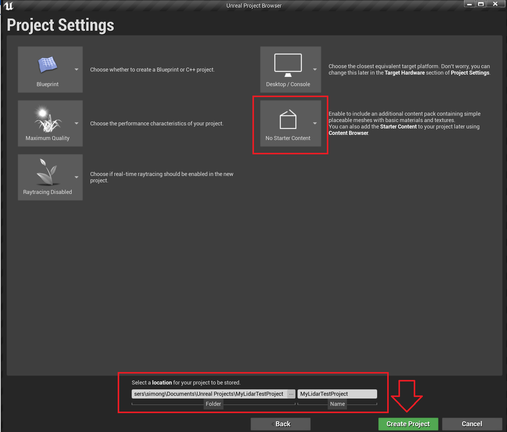
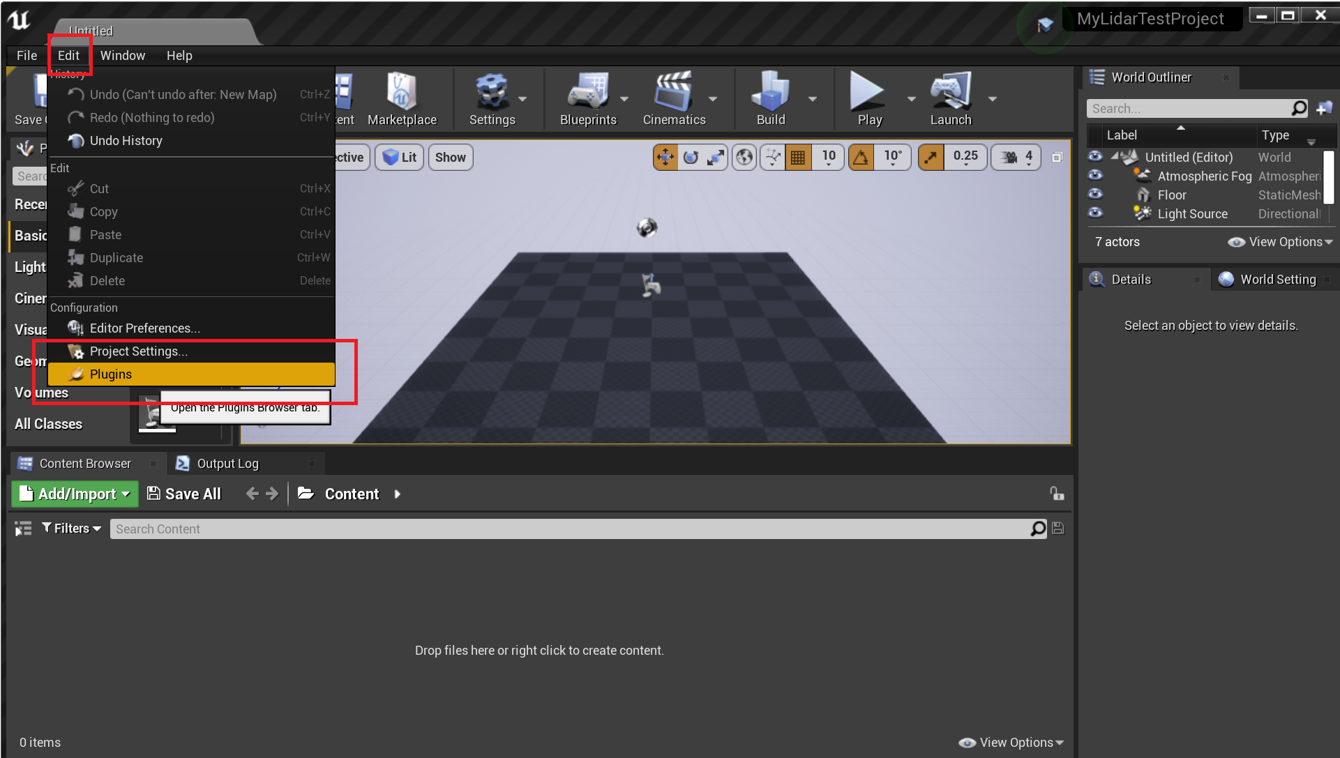
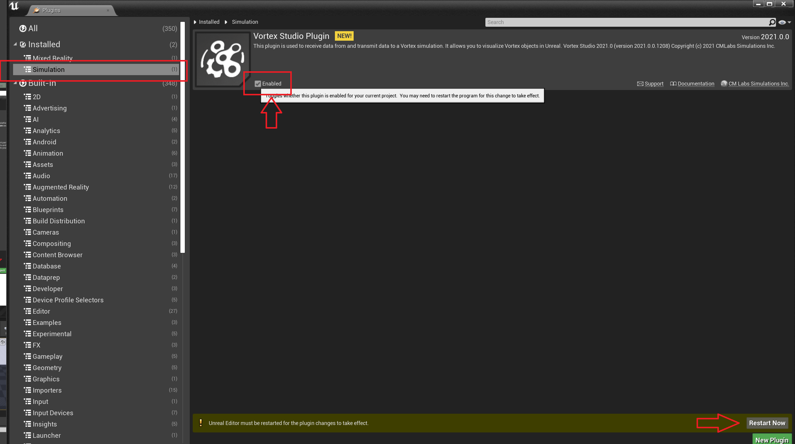
- Enable the Vortex Plugin, then restart the Unreal Editor.
- Copy the Mechanism to the Content folder of the Unreal project
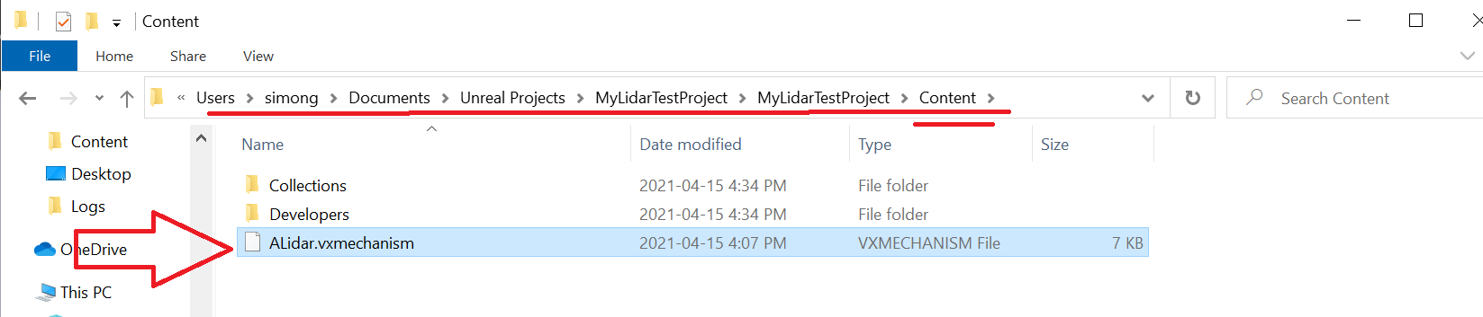
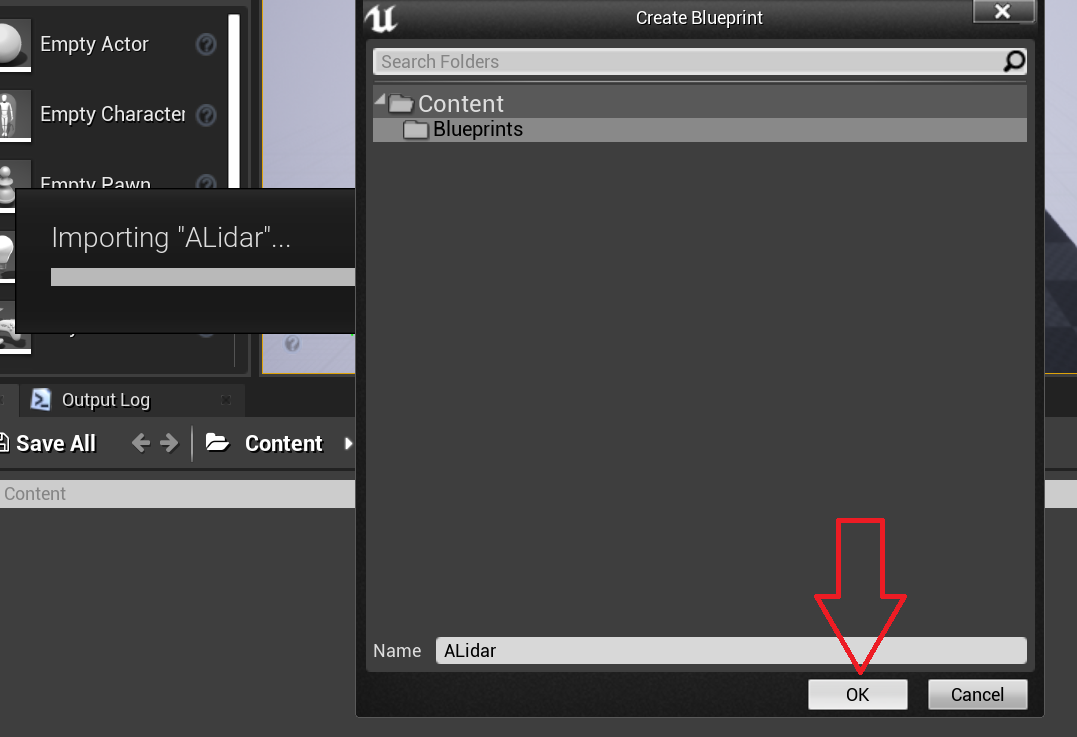
- Drag-and-drop the Mechanism file into the Unreal project asset browser

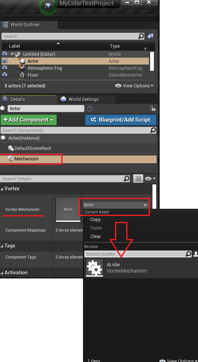
- Add an empty actor to the level and add a Mechanism actor component to that actor.
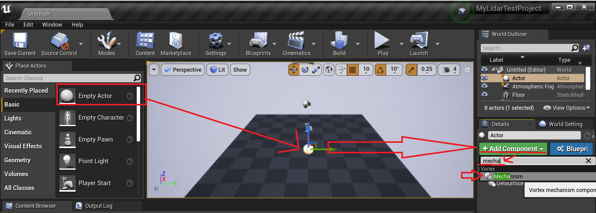
- Assign the imported Lidar vxmechanism file to the Vortex Mechanism property of the Mechanism actor component
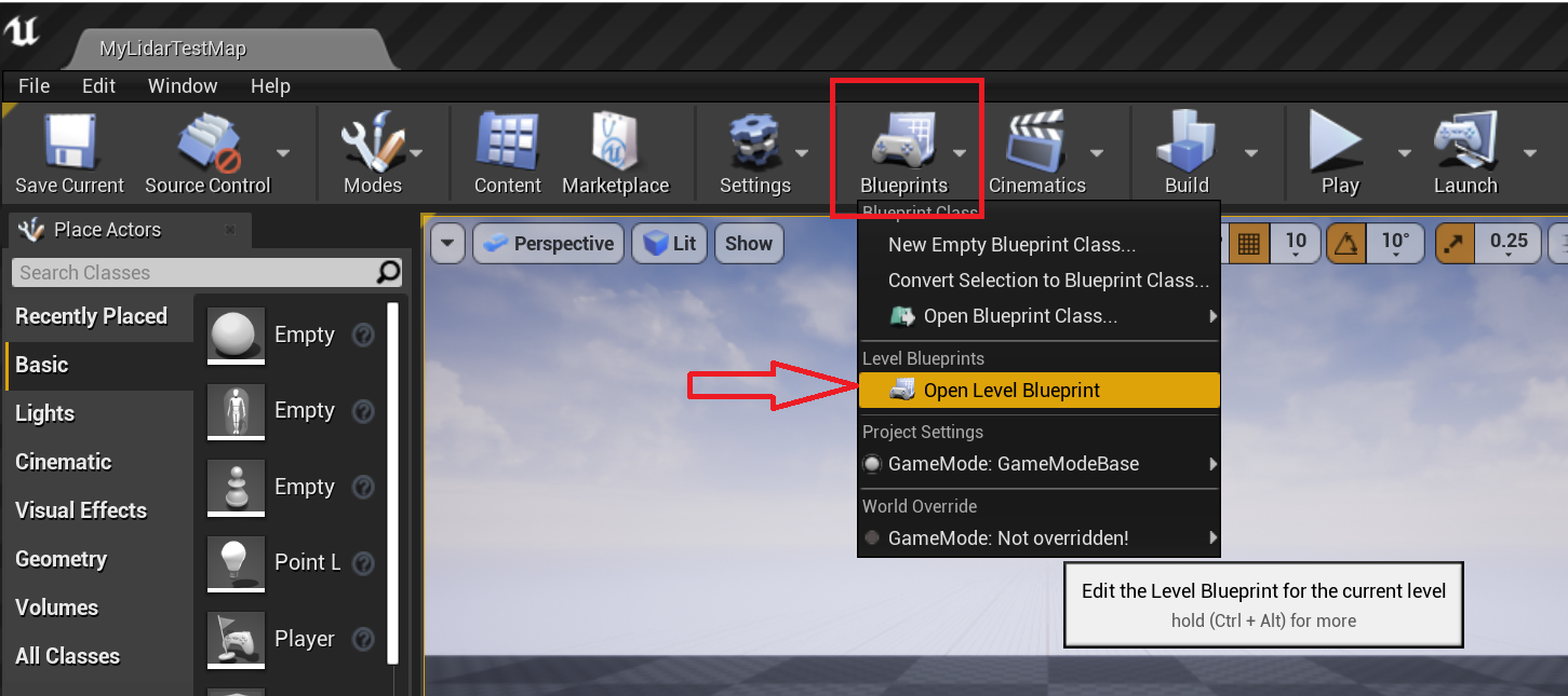
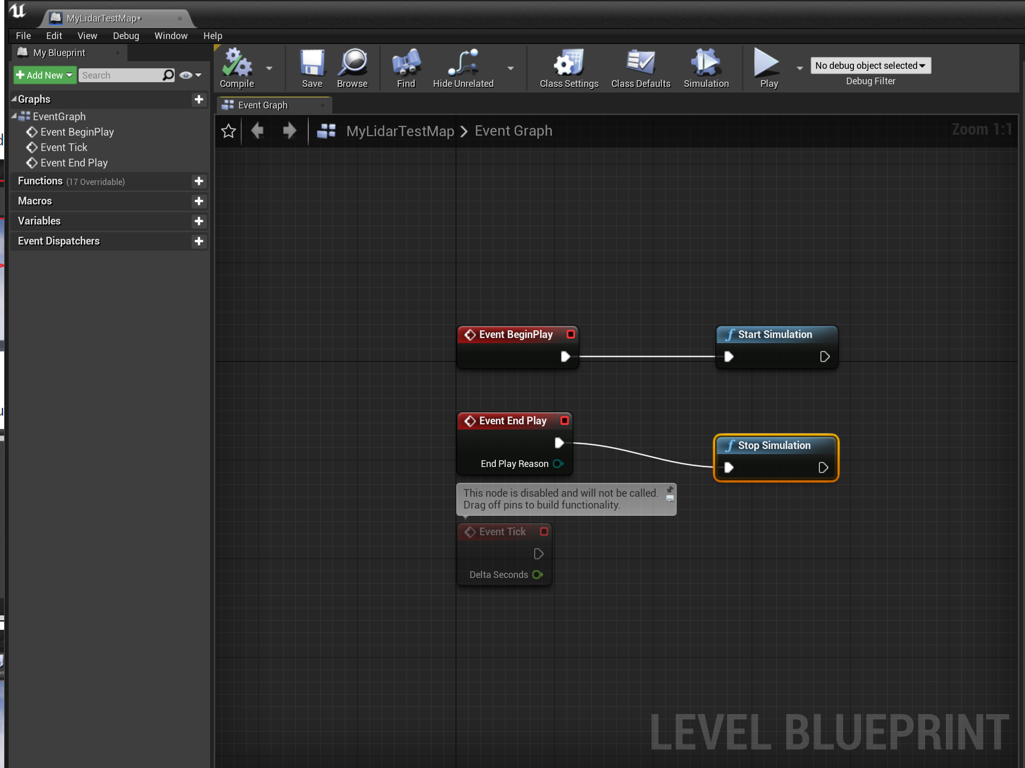
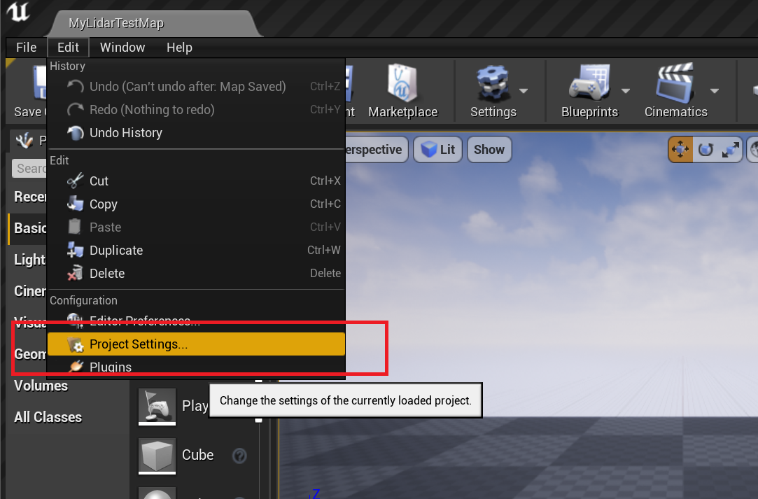
- Open the level blueprint and add the logic to start the vortex simulation on begin play and end the simulation on end play
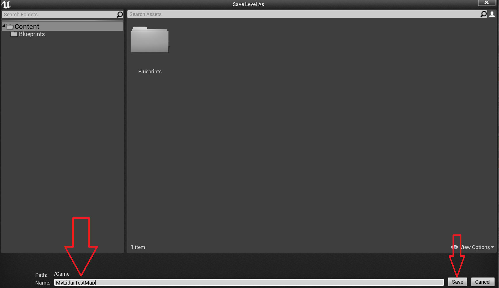
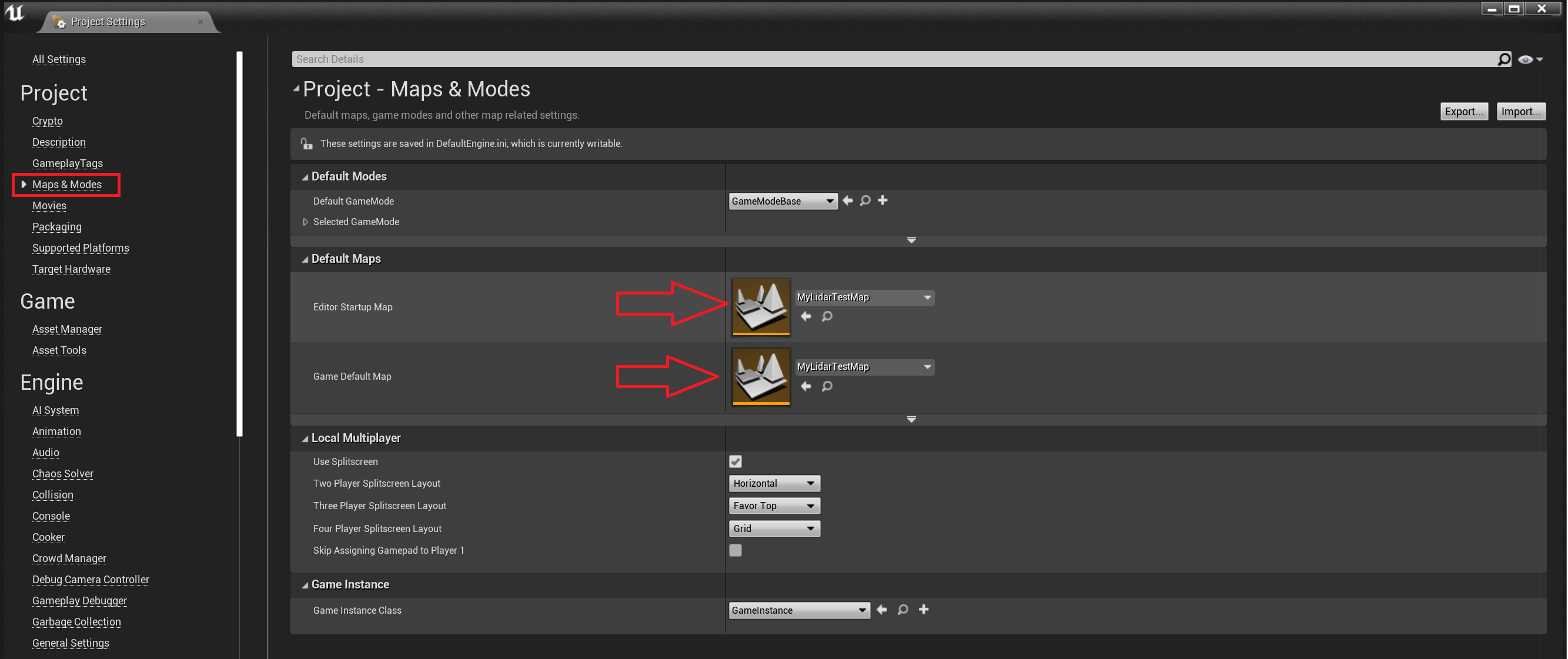
- Save the Level using CTRL+S and configure the default level to launch on play. Then Save All by doing CTRL+SHIFT+S.
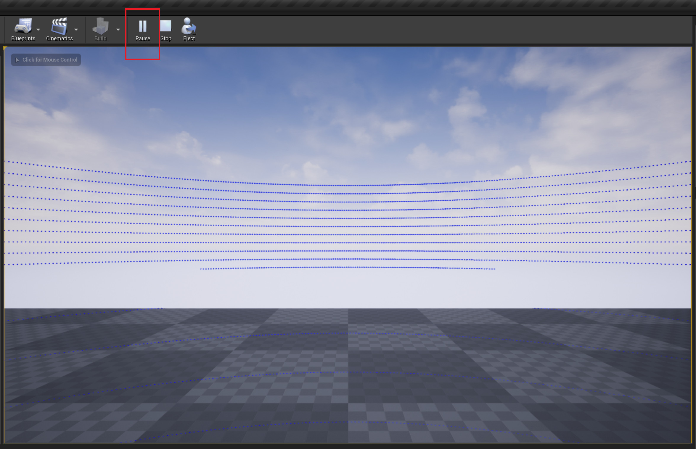
- Hit Play and you should see the Lidar visualization accessories (hit points).
Python Example
This example shows how to generate an image from the captured distance field in Python using Pillow. Because the default Python interpreter provided by Vortex doesn't include Pillow, make sure to follow these steps to use your own Python environment.
The following example is in Python 3. To use with Python 2, simply rename the Vortex module to VxSim.
Note that because the sensor processing is done asynchronously, this wont yield any result at the start of the simulation.
import Vortex
import PIL.Image
import os
import struct

{...}

def saveLidarSensorDistanceField():
    # Here, inputLidarSensor is an input extension field to which the depth camera is connected
    distanceFieldVectorFloat = inputLidarSensor.getOutput("Distance field").toVectorFloat()

    width = int(inputLidarSensor.getParameter("Horizontal step resolution").value)
    height = int(inputLidarSensor.getParameter("Number of channels").value)
    maxRange = inputLidarSensor.getParameter("Range").value

    # Convert distance field into row-major float values normalized in the [0, 255] range for Pillow.
    tempBuffer = [0] * width * height
    column = 0
    row = 0
    for i in range(0, width * height):
        normalizedValue = distanceFieldVectorFloat[i] / maxRange * 255
        tempBuffer[(width - column - 1) + (height - row - 1) * width] = normalizedValue

        row += 1
        if row == height:
            row = 0
            column += 1

    depthImageBuffer = bytes(struct.pack('%sf' % len(tempBuffer), *tempBuffer))

    pilImage = PIL.Image.frombytes("F", (width, height), depthImageBuffer)
    pilImage = pilImage.convert("RGB") # Convert the image into a saveable format

    # The image is ready to be saved
    pilImage.save("distanceField.png")
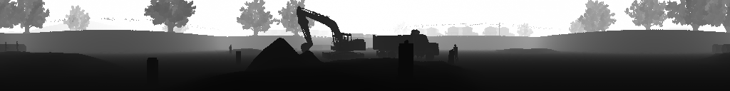
Using these parameters:
- Number of channels: 128
- Range: 100m
- Horizontal FOV Start: -180°
- Horizontal FOV Length: 360°
- Vertical FOV upper bound: 20°
- Vertical FOV lower bound: -20°
- Horizontal step resolution: 1024
The following image is produced:
Depth Camera
The Depth Camera is a perspective camera that captures the distance of objects within its visual range and provides the captured data as an output.

Parameters
| Name | Description |
|---|---|
| Image Width | Width of the captured depth image. |
| Image Height | Height of the captured depth image. |
| Field of View | Vertical field of view of the depth camera. |
| Framerate | Frequency at which a new depth capture is produced. |
| Maximum Depth | Maximum range of the depth capture. Any object beyond this will be output as the maximum value. |
Inputs
| Name | Description |
|---|---|
| Parent Transform | Parent transformation matrix of the sensor. Connect the Parent Transform to the World Transform output of some other mobile object (e.g., a Part) in order to make the Depth Camera follow this parent object. |
| Local Transform | Local transformation matrix of the sensor. Use it to place the sensor relative to its parent object. The sensor follows the typical Vortex convention: X-forward, Y-left and Z-up. |
Outputs
| Name | Description |
|---|---|
| Depth Image | Depth image resulting from the latest capture. This is a float array where each float represents a depth value from 0 to the "Maximum Depth" value, in meters. The order is row-major and the first value is mapped to the lower-left corner of the image. |
Unreal Engine
No additional steps are required to setup the Depth Camera in Unreal Engine once it has been setup in your Vortex Studio mechanism. Simply add your Vortex Studio mechanism to an Unreal project and start the simulation (the Unreal project must also have been setup correctly as described in Vortex Studio Plugin for Unreal). When the simulation starts, there is a small warm-up period (a couple of simulation steps) during which no data is produced. Afterwards, the Depth Camera will start producing captures.
Python Example
This example shows how to save the captured depth image in Python using Pillow. Because the default Python interpreter provided by Vortex doesn't include Pillow, make sure to follow these steps to use your own Python environment.
The following example is in Python 3. To use with Python 2, simply rename the Vortex module to VxSim.
Note that because the sensor processing is done asynchronously, this wont yield any result at the start of the simulation.
import Vortex
import PIL.Image
import os
import struct

{...}

def saveDepthCameraTexture():
    # Here, inputDepthCameraExtension is an input extension field to which the depth camera is connected
    depthImageVectorFloat = inputDepthCameraExtension.getOutput("Depth Image").toVectorFloat()
    width = inputDepthCameraExtension.getParameter("Image Width").value
    height = inputDepthCameraExtension.getParameter("Image Height").value
    maxDepth = inputDepthCameraExtension.getParameter("Maximum Depth").value

    # Vortex outputs depths in meters, while PIL expects values in the [0, 255] range.
    temp = []
    for i in range(0, width * height):
        temp.append(depthImageVectorFloat[i] / maxDepth * 255)
    depthImageBuffer = bytes(struct.pack('%sf' % len(temp), *temp))

    pilImage = PIL.Image.frombytes("F", (width, height), depthImageBuffer)
    pilImage = pilImage.convert("RGB") # Convert the image into a saveable format

    # The image is ready to be saved
    pilImage.save("depthImage.png")
Color Camera
The Color Camera is a perspective camera that captures the world and makes the result available for reading.
Parameters
| Name | Description |
|---|---|
| Image Width | Width of the captured image. |
| Image Height | Height of the captured image. |
| Field of View | Vertical field of view of the color camera. |
| Framerate | Frequency at which a new capture is produced. |
Inputs
| Name | Description |
|---|---|
| Parent Transform | Parent transformation matrix of the sensor. Connect the Parent Transform to the World Transform output of some other mobile object (e.g., a Part) in order to make the Color Camera follow this parent object. |
| Local Transform | Local transformation matrix of the sensor. Use it to place the sensor relative to its parent object. The sensor follows the typical Vortex convention: X-forward, Y-left and Z-up. |
Unreal Engine
No additional steps are required to setup the Color Camera in Unreal Engine once it has been setup in your Vortex Studio mechanism. Simply add your Vortex Studio mechanism to an Unreal project and start the simulation. When the simulation starts, there is a small warm-up period (a couple of simulation steps) during which no data is produced. Afterwards, the Color Camera will start producing output data.
Python Example
This example shows how to save the captured image in Python using Pillow. Because the default Python interpreter provided by Vortex doesn't include Pillow, make sure to follow these steps to use your own Python environment.
The following example is in Python 3. To use with Python 2, simply rename the Vortex module to VxSim and the bytes(...) function to buffer(...).
Note that because the sensor processing is done asynchronously, this wont yield any result at the start of the simulation.
import Vortex
import PIL.Image
import os

{...}

def saveColorCameraTexture():
    # Here, inputColorCameraExtension is an input extension field to which the color camera is connected
    colorCamera = Vortex.ColorCamera.dynamicCast(inputColorCameraExtension)
    imageBytes = bytes(colorCamera.getImageBytes())

    width = inputColorCameraExtension.getParameter("Image Width").value
    height = inputColorCameraExtension.getParameter("Image Height").value

    pilImage = PIL.Image.frombytes("RGB", (width, height), imageBytes)

    # The image is ready to be saved
    pilImage.save("image.png")