Network Communication Interface
- DEVOPS
The following UDP extensions are available:
UDP Module
In order to enable UDP network communication, you must first add the UDP Module to your Setup file. The UDP Module manages all UDP send and receive extensions (see below).
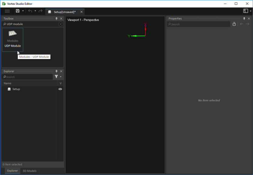
To add a UDP Module:
- In your Setup file, select Modules in the Toolbox.
- Double-click UDP Module to add it to your setup.
- If desired, rename the UDP Module in the Name field of its Properties panel.
UDP Receive
In order to receive communications from external applications or devices using UDP, you must add a UDP Receive extension to your simulation.
To add a UDP Receive extension:
- In your scene or mechanism, select Network in the Toolbox.
- Double-click UDP Receive to add it.
- Right-click the UDP Receive extension in the Explorer panel, then select Edit from the menu to add output data.
- In the resulting window, click Add. A new output row appears in the table.
- Edit the name of the output.
- Click in the Type field to open a drop-down list of possible data types for your output field (e.g., double, int32, Boolean).
- Click in the Physical Dimension field to open a drop-down list of possible dimensions for your output field (e.g., length, volume, mass).
- Add as many output fields as required, then click Ok.
In the UDP Receive extension's Properties panel, you will see the following fields.
- Inputs
- Debug
- Log Traffic: When selected, adds information to the application log.
- Debug
- Outputs
- Output data: This section displays the output data (via the Edit functionality mentioned above ) in the specified data type.
- Stats
- Bound: Indicates whether the extension has made the connection through the socket.
- Packets: Displays the number of packets communicated with the device.
- Bytes: Displays the amount of bytes communicated with the device.
- Parameters
- Local Address: Shows the source IPv4 address from which to send data. The default address (127.0.0.1) sets the address to the localhost.
- Local Port: Displays the source port from which to send data.
- Auto Assign Remote: When selected, automatic remote port and IP addressing is allowed.
- Remote Address: Displays the source from which to receive data. The default address (0.0.0.0) enables the acceptance of all UDP packets from any accessible computer. If set to a specific IP address, only packets arriving from that address are received.
- Remote Port: Shows the port of the target computer.
- Device ID: This section is filled in automatically by the module, providing identification information for the communicating device.
UDP Send
In order to send communications to external applications or devices using UDP, you must add a UDP Send extension to your simulation.
To add a UDP Send extension:
- In your scene or mechanism, select Network in the Toolbox.
- Double-click UDP Send to add it.
- Right-click the UDP Send extension in the Explorer panel, then select Edit from the menu to add input data.
- In the resulting window, click Add. A new input row appears in the table.
- Edit the name of the input.
- Click in the Type field to open a drop-down list of possible data types for your input field (e.g., double, int32, Boolean).
- Click in the Physical Dimension field to open a drop-down list of possible dimensions for your input field (e.g., length, volume, mass).
- Add as many input fields as required, then click Ok.
In the UDP Send extension's Properties panel, you will see the following fields.
- Inputs
- Input data: This section displays the input data (via the Edit functionality mentioned above ) in the specified data type.
- Debug
- Log Traffic: When selected, adds information to the application log.
- Outputs
- Stats
- Bound: Indicates whether the extension has made the connection through the socket.
- Packets: Displays the number of packets communicated with the device.
- Bytes: Displays the amount of bytes communicated with the device.
- Stats
- Parameters
- Auto Assign Locals: When selected, automatic local port and IP addressing is allowed
- Local Address: Shows the source IPv4 address from which to send data. The default address (127.0.0.1) sets the address to the localhost.
- Local Port: Displays the source port from which to send data.
- Remote Address: Remote IPv4 address to which data is sent.
- Remote Port: Shows the port to which data is sent.
- Device ID: This section is filled in automatically by the module, providing identification information for the communicating device.
Network Communication Add-on (UDP)
Network Communication Add-on is a device that allows communication with external applications or devices over User Datagram Protocol (UDP).
The Network Communication Add-on devices can be created in both the content and the application setup as a device. The protocol used is the same as the Real-Time UDP for MATLAB and Simulink.
Note If you are connecting to an external device or application (e.g., Simulink), this section and the Network Extensions above should provide you with enough information to set it up to communicate with Vortex® Studio using UDP.
This table shows the direct conversion between the Vortex type and the external type.
| Vortex Type | External Type | Bytes |
|---|---|---|
| double | double | 8 |
| float | single | 4 |
| int | int32 | 4 |
| unsigned int | uint32 | 4 |
| short | int16 | 2 |
| unsigned short | uint16 | 2 |
| char | int8 | 1 |
| unsigned char | uint8 | 1 |
| bool | boolean | 1 |
Adding Network Communication as a Device
In order to add Network Communication as a device, the add-on needs to be configured in the application setup.
First, open the Vortex Studio Editor and create a new setup or open an existing one.
The second step is to add the UDP Module by searching in the Toolbox and double-clicking on UDP Module.
The UDP Module manages all the UDP send and receive extensions. See Network Extensions for more information.
Similarly to the module, the send and receive extensions can be added by searching UDP Send or UDP Receive in the Toolbox.
Once an extension is added, it is possible to modify its properties in the Properties panel.
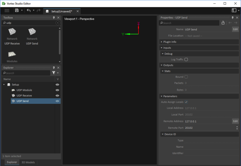
In the Properties panel, you will find the following information:
- Networking information (address/port)
- Device ID
- List of data to be sent/received
Parameters
The local address and port identifies the host IP address and port, while the remote address and port describes the IP address and port of the external application or device communicating with Vortex Studio Editor.
The Device ID lists the information concerning the device, which is used in order to identify the device. This will be filled automatically by the module.
Received and Sent Data
The list of data to be sent or received can be found in the Outputs section when dealing with the UDP Receive extension, and Inputs panel when dealing with the UDP Send extension.
As the name suggests, the UDP Receive extension will receive data, while the UDP Send will send data according to this data list.
To add data, right-click on the extension and select Edit. This window is used to add and remove fields of data, e.g., inputs and outputs.
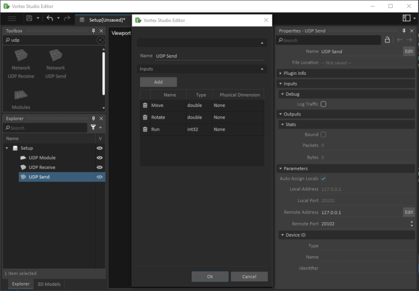
In the example shown above, the UDP Receive extension will receive two double values (Move and Rotate) and one int32 value (Run).
Note The order of the data in the list will dictate the structure of the sent/received data. However, the names have no impact and are simply there to identify them locally.
Mapping the Device
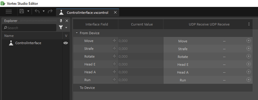
Once the communication device has been created in the application setup, it can be mapped in the Vortex Studio Player via The Control Presets tab.
Mapping allows you to connect data fields to a Control Interface, which in turn is connected to a mechanism.
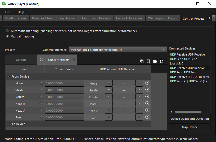
In the previous image, the UDP Receive device is associated with "ControlInterfaceInputs".
Once the data fields are properly associated, the data will automatically be transmitted to the Control Interface.
It is also possible to set the communication device as a Control Interface's default device in Vortex Studio Editor. This means that the Control Interface will automatically associate this device when the content is loaded in Vortex Studio Player.
Creating in the Content
There must be a UDP Module located in the application setup file (editor.vxc) in order to make the extensions functional in the Vortex Studio Editor. The extensions are not functional when the name is grayed out.
In order to add the Network Communication device add-on to the content (mechanisms and scenese), it is first of all necessary to open Vortex Studio Editor and create/open a scene or mechanism.
Once the content file open, you can add the extension by searching in the Toolbox. The properties can then be modified accordingly.
Note UDP Module must be added to the proper node of the setup used by the simulator to activate the network extensions of the content.
For example, a Connection Container can be added in the same object as the UDP extension. In the same example, a Controllable Human is also added to the content in order to demonstrate data field connections.
Data fields from the Human Control are added to Connections.
Once the data fields are added to the Connections Container, the fields can be linked together, as seen in the next image.
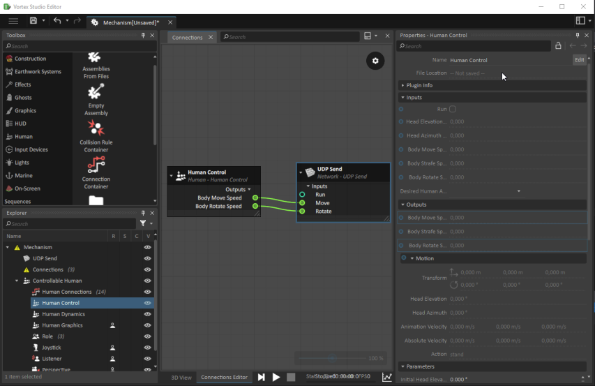
The data sent to the external application or device will be transferred to the Controllable Human's Body Move Speed and Bode Rotate Speed.