Control Interface
- DEVOPS
 This section describes how to enhance your simulation with predefined device systems.
At the Mechanism or Scene level, Control Interfaces facilitate communication between content in the Editor and hardware inputs. The Control Interface functionality allows you to create and edit a Control Interface for multiple devices and their default device mappings. Additional device mappings are available in the Vortex® Studio Player Control Presets tab.
Overview
The following is an overview of the Control Interface panels and fields.
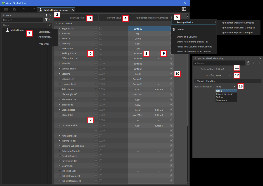
- Name of the Control Interface
- Right-Click the name and select Edit Fields... to add and remove inputs/outputs from the Control Interface.
- Right-Click the name and select Add Device... to add a device to the Control Interface.
- Right-Click the name and select Properties to show the Control Interface's file location.
- Filename of the Control Interface
- Name of the Control Interface fields
- To manage fields from the Control Interface, see Edit Fields....
- Current value of the Control Interface fields
- For "From Device" fields that have a valid device mapping, the value is updated when user actuates the device. For "To Device", the value can be modified by the user and sent to the device.
- Values can be:
- Boolean (indicated by a box)
- Integer (indicated by a value without decimals)
- Double-precision floating point (indicated by a value with decimals)
- Device menu
- Select Reassign Device to swap out one device for another on an already-defined device mapping
- Select Delete to remove the device and its device mapping.
- Column width operations (useful when there are many mapped devices)
- Select Shrink This Column to shrink this column to have more room to work on other columns
- Select Shrink All Columns Except This to shrink all other columns except this one to have more room to work on this column
- Select Resize Column To Fit Content to expand or shrink this column to match the content's size
- Select Resize All Columns To Fit Content to expand or shrink all columns to match the content's size
- Add Row button: Select to add an additional device mapping row on the same Control Interface field. This is useful when you have multiple buttons on one device for the same Control Interface field.
- Remove Row button: Only available on added rows. Click to remove additional device mapping(s) from a Control Interface field.
- Mapped device cell: Click to map a device button to a Control Interface field by either actuating the device itself or by using the Properties panel drop-down (see #11).
- Mapped device modifier: Click to map a device button to a Control Interface as a modifier on the actual mapped device actuator. Use the Properties panel drop-down (see #12).
- Calibration button (see Device Mapping Calibration)
- Mapped device actuator (Properties panel drop-down):
- Expand to see the available list of axes or buttons on the selected device
- Select to map the actuator
- Mapped device modifier (Properties panel drop-down)
- Expand to see the available list of actuators, buttons or other, on the selected device
- Select to use as modifier
- Transfer Function
- Select None to directly pass the device data through with no transformation.
- Piecewise Linear (see Device Mapping Calibration): Use this to convert non-standard device values to custom device value. Default value at rest is "Destination Value for Source Rest Value".
- ToBool maps the numeric device value to a Boolean (false, true) value.
- Default value at rest is "false".
- "Source Deadband Range" is the threshold at which the device value results in the Control Interface field value being "true" instead of "false".
- "Source Rest Value" is the neutral reference on the device value.
- "Inverted Flag" applies a "NOT" to the resulting Control Interface field value. Default value is then "true".
- ToNumeric converts a Boolean device value to a numeric value. The default resulting value is 0.000.
Edit Fields
To edit the fields of a Control Interface object, right-click on the object in the Explorer panel and select Edit Fields... from the menu.
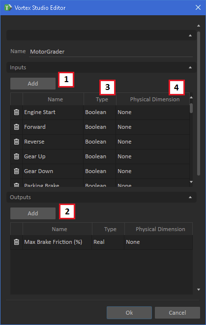
- Add an Input field (From Device)
- An actuator, button, axis, etc.
- Add an Output field (To Device)
- An LED, dial, LCD display, etc.
- Type of the field
- Integer, Boolean, Real.
- Physical Dimension of the field
- In SI units
Device Mapping Calibration
The Device Calibration Dialog is used to modify the Piecewise Linear transfer functions of the From Device fields. It can be used in two modes: manual or automatic.
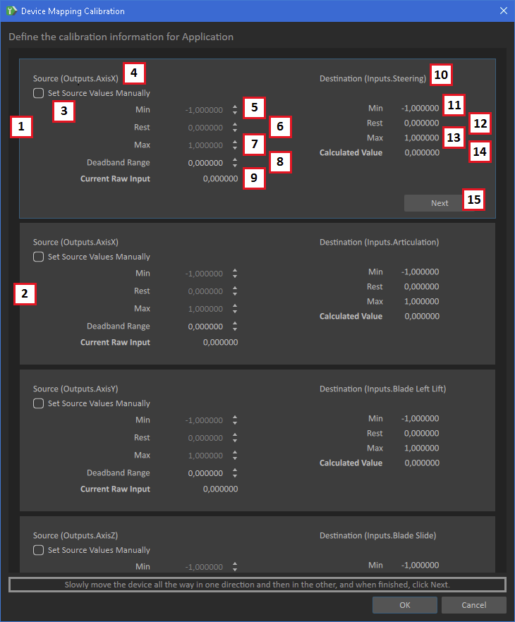
- A device mapping.
- Another device mapping on a different Control Interface field or another row for the same input/output
- Set Source Values Manually specifies transfer function minimum, maximum and rest values manually
- Device name
- Source value minimum
- Source value rest
- Source value maximum
- Source value deadband
- Current source value
- Destination on the Control Interface
- Destination value minimum
- Destination value rest
- Destination value maximum
- Current destination value
- Cycle through the device mappings on this page. Alternatively, you can click the desired mapping to select it.
Control Interface Linker (Scene and Mechanism Documents)
Once an interface is fully defined, it must be added to a mechanism or scene using the Toolbox (Basics > Control Interface From File).
Right-Click on the Control Interface and select Edit Links to link the inputs/outputs of the Control Interface to properties in your mechanism or scene.
As in connections, linking is done by dragging and dropping fields from the Properties panel onto the respective Control Interface Linker rows.

- Control Interface field name
- Field type
- Currently linked extension field. This can be a field of the mechanism (or scene), or any extension it contains.
- Drag and drop fields from the Properties panel to #5, in this example to link the Control Interface Automation field to this mechanism's extension field (or scene)
- Properties panel field to add to the Linker. See #4 above.