Connection Editor
- DEVOPS
 Connections are mappings between parameters that are internal to Vortex® and parameters that are piped into Vortex through an extension.
Connections can be created at both the mechanism and scene level, but all connections defined on a mechanism are local to that mechanism. The scene has its own discrete set of connections.
Connections are made via the Connections Editor Node Graph View or List View.
Node Graph View
In the Node Graph view, connections between extensions' inputs and outputs are visually represented as circular nodes connected by colored lines.
Boxes and Fields
A connection container is the element wherein you organize your connections.
To create a new connection container:
- Select Basics from the Toolbox.
- Double-click Connection Container. It now appears in the Explorer panel.
- In its Properties panel, you can rename the container through its Name field.
To add fields to the container:
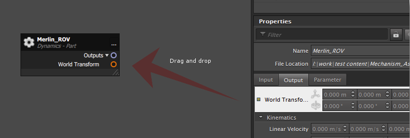
Select an extension from the Explorer panel or the 3D View so that its Properties panel opens.
If the connection container is already open, single-clicking the extension in the Explorer panel reveals the Properties panel of that extension while keeping the container open in the main window.- Drag and drop the desired property from the Properties panel onto the graph.
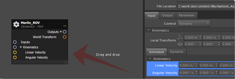
A new container box related to the extension appears at the drop location, containing its associated fields. If a box related to the extension has previously been added, the newly dropped fields are added to that existing box.
|
| Dragging a property to the connection container |
|---|
|
| Adding more properties to an existing container box |
|---|
To remove a field from a box:
- Hover the mouse over the field.
- Click the delete icon that appears.
To remove an entire container box:
- Select the desired box. (Hold down Ctrl to select multiple boxes.)
- Right-click and select Remove from the menu.
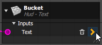
To view field properties:
- Hover over a field in a container box.
- Click the arrow that appears to open its Properties panel.
To move and resize a container box:
- Click the header or any empty space in the box.
- Drag the box to a new position in the container.
- Click the bottom-right corner of the box.
- Drag the corner to resize the box.
To navigate the connection container:
- Scroll the mouse wheel to zoom in or out at the mouse cursor's position in the connection container.
- Hold down the mouse wheel and move the mouse to navigate around the connection container.
Connections
The main benefit of the connection container is to see at a glance the connections between inputs and outputs in a visually-simple way.
You can create connections between two fields in two ways:
- Connection between two fields already added to the container.
- Connection between a field already added to the container to one that is not.
To connect two fields already added to the connection container:
- Click and hold on the desired connector. Inputs are aligned on the left side of a container box, outputs on the right.
- Drag the mouse to the desired end point. A preview connection line appears, while incompatible fields become shaded.
- Release the mouse button on a compatible field to complete the connection.
To connect a field already added to the container to one that is not:
- Select an extension from the Explorer panel or the 3D View.
- Drag and drop the desired field from that extension's Properties panel onto a compatible field in the container box.
To delete connections:
- Select an existing connection by clicking on it. You can select multiple connections by dragging a box around them, or by holding Ctrl and selecting them one at a time.
- Right-click and select Remove.
To move a box to another container:
- Select the boxes to move.
- Right-click one of the selected boxes.
- Do one of the following:
- Select Move to new container... to create a new container and move those boxes to it. You will need to provide a name for the container in the resulting dialog box.
- Select Move to other container... to move the boxes to an existing container. You will need to specify the existing container in the resulting dialog box by selecting it from the Explorer panel.
The selected boxes are now located in the other container, while maintaining their existing connections across containers.
To align container boxes:
- Select multiple boxes.
- Right-click one of the selected boxes and in the Alignment sub-menu, select one of the following:
- Align Left
- Align Horizontal Center
- Align Right
- Align Top
- Align Vertical Center
- Align Bottom
- Space Horizontally
- Space Vertically
Alternatively:
- Right-click in the connection container or a box in the connection container.
- In the Auto Layout sub-menu, select one of the following:
- Directly connected items: auto-aligns the selected box with its directly connected boxes.
- All connected items: auto-aligns the selected box with all its directly and indirectly connected boxes.
- All items: auto-aligns all the boxes in the container.
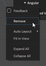
To mark connections as feedback loops:
- Select a connection line.
- Right-click and check the Feedback box.
The connection line is now dashed to indicate it is a feedback loop.
The connectors are color coded according to the data type of the fields they represent. The table below describes the color mapping between connectors and their data types.
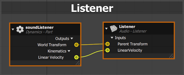
Frames
A frame is a convenient feature for organizing container boxes of related extensions. Grouping related boxes together in a common area is particularly useful when the connection container becomes very large.
To add a frame:
- Select at least two container boxes (or existing frames, to create nested frames).
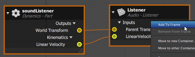
- Right-click and select "Add to Frame".
- In the resulting dialog box, name the frame.
To add a container box or another frame to an existing frame:
- Select the desired boxes or frames.
- Drag until the frame changes color to indicate that the item can be dropped in an existing frame.
The selected boxes or frames are now included in the existing frame.
To remove container boxes or frames from a frame:
- Select the boxes or frames to be removed from a frame.
- Right-click and select Remove from Frame. (Alternatively, hold Ctrl, and drag and drop the box or frame out of the frame.
To move and resize a frame:
- Click the header of the frame.
- Drag the frame to a new position in the container.
Items in the frame can be independently moved or resized. The position and size of the frame automatically adjusts to fit its contents.
To delete a frame:
- Select a frame.
- Right-click and select Remove.
Note that this also deletes all elements within that frame.
Options Menu
The connections container has an Options menu giving you greater control of the presentation of the container boxes. You can access the Options menu by clicking ![]() in the top-right corner of the container window.
in the top-right corner of the container window.
The Options menu contains the following functions:
- Display
- Show Object Type: Checking this box includes a subtitle for the container box displaying its object type.
- Show Fields Hierarchy: Checking this box adds fields labels to the container boxes, i.e., input, output.
- Colorized By Data Type: Checking this box add colors to the connection lines, each color reflecting a different data type.
- Isolation
- None: All boxes and connections are displayed.
- Show Directly Connected: Selecting this option grays out all the boxes. Clicking a box then highlights that box and only boxes and connections directly connected to it.
- All Connected: Selecting this option grays out all the boxes. Clicking a box then highlights that box and only boxes and connections directly and indirectly connected to it.
- Lock Result: Checking this box locks what you see in the connection container. Selecting other boxes does not change the display.
List View
In addition to the Node Graph view, you can also view and manage connections in the List view.
To switch to the connections' list view:
- Select a connections container from the Explorer panel.
- In the top-right corner of the Connections Editor tab, click the drop-down arrow.
- Select List View.
Editing Existing Connections
This procedure explains how to edit the set of connections defined on a mechanism or scene in the Connection Editor, using the List view.
Open the mechanism or scene containing the connections.
Right-click the connections container in the Explorer panel and select Edit from the context menu. The Connections Editor loads in the main panel (where the 3D View usually appears). At the top of the Connection Editor, use the Connection tabs to select the appropriate connection container.
- Switch to the List view (described above).
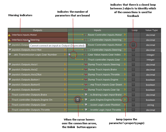
If you want to see the Properties panel of one of the connected parameters, click the Jump icon (yellow arrow).
To undock the Connection Editor, right-click anywhere on the Connection Editor and click Undock or by dragging and dropping the panel from the tab at the bottom of the window and moving it somewhere else.
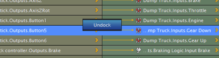
This allows you to see the contents of the 3D View and the Connection Editor at the same time and move it around the workspace. To dock it again, right-click over top of the list of connections and click Dock or drag inside the dialog and drop it over the main window.
Creating a New Connection
All connections for a mechanism or scene are listed in a single container called the Connection Editor, where you connect parameters to the inputs and outputs. As you add parameters to the list, the Value Type is specified by Vortex® so that you cannot connect two parameters of different types.
To add a new connection:
- Open the Connections list contained in the mechanism or scene to which you want to add connections.
- In the Explorer tree, click any of the following:
- Vortex objects that contain properties (parts, constraints, controllers, wheel components, and collision geometries)
- VHL interfaces
- Imported extensions (for example, a joystick or camera extension)
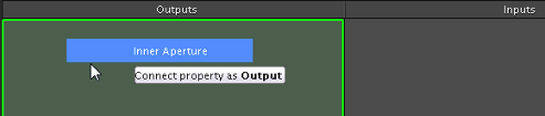
From the Properties panel, drag and drop the property you want to connect as an output onto the Outputs section of the Connection Editor.
- In the Explorer tree, click another object to display their properties in the Properties panel.
From the Properties panel, drag and drop the property you want to connect as an input onto the Inputs section of the Connection Editor. To bind more than one input parameters to an output, drag and drop the second input parameter over the first input parameter in the list.
Warning Connections cannot be made between parameters that both belong to objects that are internal to Vortex; otherwise, the following message appears:
- If you need to break the link between the connection and the source of the parameter, follow these steps:
- Hover over the arrow in the Inputs column of the connection you want to disconnect.
- When you see the lock icon, click on it. If only one input parameter was defined, the entire row disappears; for multiple parameters, the output parameter still appears in the Connection Editor with the remaining parameter(s).
- To delete the entire connection from the list, select the row you want to delete and press the Delete key.