Modeling a Complex Reeving System
- DEVOPS
Note: This is an advanced topic. This page is only applicable if you want to switch between reeving using mechanism configurations at the beginning of a simulation, not during runtime.
It is possible to model a crane with a complex reeving system in Vortex® Studio Editor. However, by including several dozen pulleys in the model, the dynamics simulation time will increase and can make it difficult for Vortex Studio Editor to run the simulation in real-time. This is due to the high number of parts and constraints needed to model the full system. To work around this limitation, we can set two different cable systems, one for the dynamics and one for the visuals.
Modeling the Dynamic Cable System
The basic idea here is to model the dynamic effect of a complex reeving system without taxing the dynamic solver in Vortex Studio too much. This is done by reducing the number of parts and constraints with a simpler cable system with fewer falls. We can then use a gear ratio constraint or a script to convert the speed and maximum torque of the winch to emulate the winch behavior with the full reeving system. As an example, let us use the following reeving system on a heavy duty offshore crane.
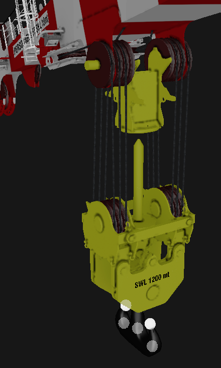
The reeving system above is essentially composed of 16 pulleys, all connected through one cable and has 12 falls. If we want to simplify the dynamic model of the crane, we can reduce the system to eight pulleys with four falls, as seen below.
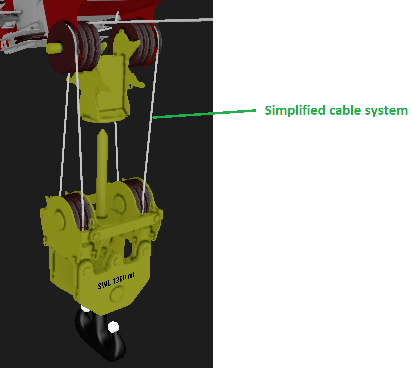
To match the behaviors of the winch and the travel speed of the cable systems between the simplified model and the real model, we apply a gear ratio of 3:1 (i.e., 12 falls to four falls) at the winch. This achieves the equivalent torque and rotation speed between the winch of the simplified simulated cable system and the winch for the real crane.
Modeling the Cable System Graphically
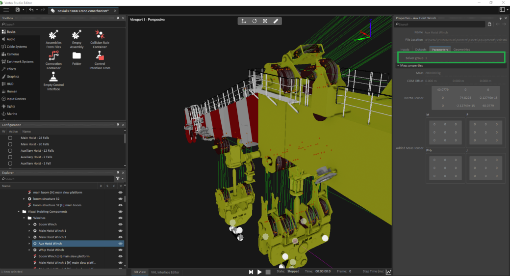
Once the dynamic modeling of the cable is done, it is preferable to visually see the complete reeving system of the crane for a training simulation. We can do this without increasing the dynamic solving time by ensuring that the parts have a purely visual effect in the simulation. This is done by modifying the Solver Group parameters of parts (see below).
For example, in the previous section, we simplified the dynamic model of the reeving. Now, we would like to visually display the cable system with the 16 pulleys.

To display the visual cable system:
- Create all the required pulleys and properly constrain them to the hook block or the crane. In our case, it would be 16 pulleys.
Set the solver group of each pulley to a group other than 0 (e.g., 1).
The solver groups are found in the Properties panel of each part. The user can change them in the .vxassembly file, for each part, or modify them by creating a VHL interface directly in the assembly or mechanism (see image below).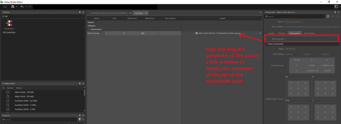
Create a Python script that will set the new solver group strength to -1.
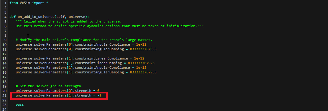 Setting the strength to -1 ensures that the pulley parts set in the new solver group do not have any physical effect on the crane and the reeving.
- Create the cable system that represents the complex reeving system.
- Make the winch of the visual cable system always pull the cables inward with relative low forces to always keep the visual cable under tension.
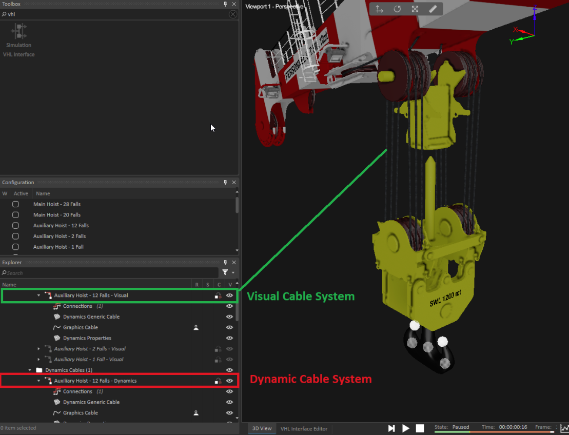
By following the steps above, we will get two cable systems in our mechanism: one dynamic cable system used to hoist the hook block up and down, and one visual cable system that allows the operator to see the full cable system.