Customizing the Cable's Appearance
This procedure explains how to customize the appearance of a cable system.
From the Explorer, click the Graphics property icon under Cable Systems folder.
The properties now appear in the Properties Panel.
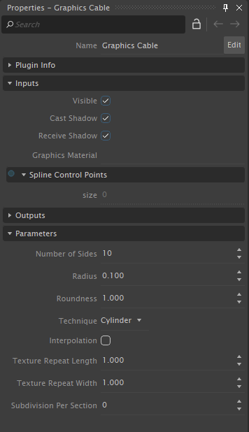
- Configure the following inputs:
- Visible: If enabled, makes the cable visible to the user. Even if the cable is not visible, it will be part of the simulation if active.
- Cast Shadow: If enabled, the cable casts shadows on other objects in the simulation.
- Receive Shadow: If enabled, shadows from other objects will be visible on the cable.
- Graphic Material: Graphics material used for rendering the cable (standard Graphics presets, such as strained steel, chain, etc.).
You can customize how the cable shape is drawn by modifying the following:
- Technique: Kind of shape to extrude along the sections of the cable (
Cylinderfor regular steel cable,Strapfor belt type cable or 2D tank tracks,Crossfor 2D chains,Linefor rope,Meshfor 3D chains or tracks). - Interpolation: Turn on interpolation, and then use Subdivision per section to smooth the cable between cable sections, thereby producing better curves.
- Technique: Kind of shape to extrude along the sections of the cable (
Modifying the remaining parameters:
Note The available fields depend on the technique selected above.
- Number of Sides: Number of sides when the extrusion technique is by cylinder.
- Radius: The radius is used when displaying the cable. This value can be different from the dynamics radius used by the collision object or the dynamics properties.
- Roundness: Roundness ratio (using 1.0 produces equal size all around).
- Graphics Geometry: Specifies the desired graphics geometry to represent the cable.
- Texture Repeat Length: Number of times the texture is repeated along the length of the cable.
- Texture Repeat Width: Number of times the texture is repeated along the width of the cable.
- Alternate Mesh Rotation: Selecting this option rotates each alternating spline section 90° (useful for creating a chain made of links).
- Subdivision Per Section: Number of subdivisions used to enhance the smoothness between each spline section. Used when interpolation is enabled.
- Mesh Overlap: Specifies the amount of a spline section that extends over the next section (in meters).