Contact Materials
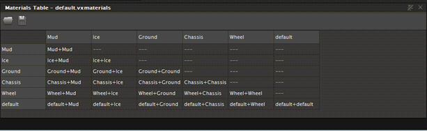
 In Vortex®, the contact material defines the behavior when two materials collide.
A mechanism has various materials; for example, in a vehicle mechanism, the wheels are made of rubber, the chassis of steel, and the bumpers of plastic.
This section discusses the concepts of materials and contacts. It also explains the tasks required for using these in a scene and the best practices to ensure that you get the most accurate results when testing and validating mechanisms.
Note For instructions on applying materials to a geometry, see Assigning a Material to a Collision Geometry.
Best Practices when Working with Materials
Always decide beforehand which Material Table will be used. If you do not select a Material Table, the default one will be used, which may not be appropriate for the test simulation.
Creating and Saving a New Material Table
You can create a new Material Table from an existing Material Table by loading it, modifying it and then saving it.
Note You can have a scene automatically load a particular Material Table by using the Material Table extension.
Warning This procedure is only recommended for advanced users as using new contact material properties will alter the simulation.
If the Material Table panel is not visible, select Material Table.
If you would like to change the table that appears in the Material Table panel, click the Load Material Table icon at the top left of the materials panel and choose a different
.vxmaterialsfile from the browser.To add a new row, follow these steps:
- In the Material Table panel, right-click the row you want to copy and select Clone material from the context menu. You can use the default or any other material row if you prefer.
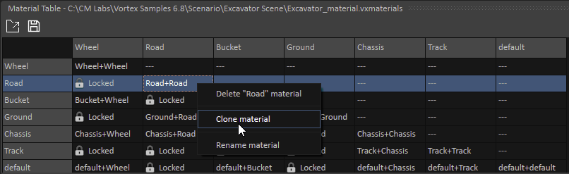
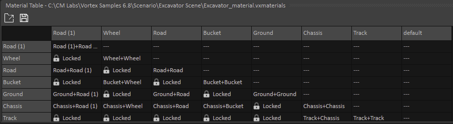
- The cloned row appears at the top of the panel with a number appended to its name. To rename it, right-click the row and select Rename material from the context menu. Notice that the new name appears in both the row and column header.
- Follow the instructions under Editing Contact Material Properties to adjust the values for the material and any of its contact material.
- In the Material Table panel, right-click the row you want to copy and select Clone material from the context menu. You can use the default or any other material row if you prefer.
To delete a row from the table, right-click the row and select Delete <material_name> material from the context menu.
When you complete the contents of the table, you can save it by clicking the Save icon at the top left of the Material Table panel.
Editing Contact Material Properties
You can change the values for a material as well as change the values for any contact material in the Material Table.
For example, you may want to increase the Restitution only on the Wheel+Wheel contact material.
From the Material Table panel, do one of the following:
- Click on a single material (for example,
Mud) to edit the material properties. - Click on a specific contact material (for example,
Mud+Wheel) to edit the contact material properties. These intersections choose the most compliant value from either of the two materials' properties. - Select an entire row or column to edit a group of contact materials.
The selected material is highlighted and the associated properties appear in the Properties panel.
- Click on a single material (for example,
In the Properties panel, edit the properties (see below).
To save these values, click the Save icon at the top left of the Material Table panel and overwrite the
.vxmaterialsfile.
Contact Reference Frame System
To understand the meaning of the different parameters in a contact material's properties, it is necessary to look at the reference frame that is part of a contact.
A contact is threaded in the same way as usual constraints, but with two differences:
- Constraint’s coordinate system (the so-called Attachment) is defined by the detection of collision.
- Properties are taken from the material table.
The coordinate system of a contact is a right-handed reference frame located at the position of contact.

The normal N is defined by the collision detection and is along the perpendicular of the separation plane between the two colliding geometries. P lies in the plane of separation, so it is perpendicular to N. Finally, s is defined by the cross product N x p. In the plane of friction, the direction of p is arbitrary. This reference frame is defined in world space.
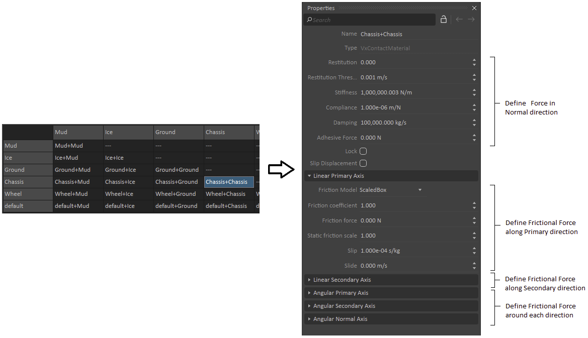
The Properties panel of a material is divided into six categories (see the figure above):
- The first category begins with the name of the contact material following by some individual properties. Each property is used to define the reaction force in the normal direction N.
- The following two categories are used to define the frictional force in the plane of contact (i.e., along p and s).
- Finally, the remaining three categories are used to define the frictional torque about each individual axis in the reference frame above (i.e., around p, s and N.
The individual properties are described below.
In the Properties panel, configure the following fields:
- Restitution: Specifies the coefficient of restitution, which is a measure of how much energy remains in an object after a bounce. A value of 0.000 is considered purely plastic (objects do not move apart after collision), while a value of 1.000 is purely elastic (objects bounce away after a collision with the same speed at which they collided). A value of 0.500 means that an object bounces half as much as its previous bounce. An object stops bouncing once the relative speed is below the restitution threshold.
- Restitution Threshold: The speed at the contact point (along the normal direction) below which an object stops bouncing (in m/s).
- Stiffness: Value that controls how much the contact compresses the object (in N/m).
- Compliance: The reciprocal of Stiffness (in m/N).
- Damping: Value at the contact point to get the system to reach equilibrium (in kg/s). As a rule of thumb, Damping should be ten times Stiffness.
- Adhesive Force: The external force applied in the normal direction needed to separate two object at the contact point (in N).
- Lock: Once a field in the Properties panel is altered, this box is checked to indicate that it has customized material properties. Unchecking this box reverts the properties to their default values.
- Slip Displacement: Check this box to activate the contact matching feature. This is required to properly model static friction.
- Linear Primary Axis, Linear Secondary Axis, Angular Primary Axis, Angular Secondary Axis, Angular Normal Axis
- Friction Model: Selects the desired friction model for the axis. Some models may ignore some of the following fields. The models are:
- Box: Contact friction force is limited by using the Friction Force parameter.
- ScaledBox: Contact friction force is limited by using Coulomb's law.
- BoxProportionalLow: Same as Box but internally will scale the Friction Force in order to limit the acceleration to the object that has the small mass.
- BoxProportionalHigh: Same as Box but internally will scale the Friction Force in order to limit the acceleration to the object that has the higher mass.
- ScaledBoxFast: Same as ScaledBox but trades accuracy for speed.
- Neutral: Flag used during the auto-combination of two VxMaterials into a VxContactMaterial. If one VxMaterial is set to Neutral, the model of the other one is used (or None, if both are Neutral).
- None: Friction is disabled for this axis.
- Friction Coefficient: Sets the coefficient of friction. This value is only used when Friction Model is set to ScaledBox or ScaledBoxFast.
- Friction Force: Sets the force of the friction. This value is only used when Friction Model is set to Box, BoxProportionalLow or BoxProportionalHigh.
- Static Friction Scale: When the contact is at rest, the static friction is at work. In such situations, the limit in the contact friction force is scaled by this multiplication factor. The value of this field should not be less than 1.000. To be considered "at rest", the speed in the contact plane must be smaller or equal to the threshold speed of the AutoSleep feature.
- Slip: When greater than 0.000, this value adds viscosity (in s/kg). If set to 0.000, the friction is dry.
- Slide: Enforces a speed (in m/s) at the contact point, working against an object stopping.
- Friction Model: Selects the desired friction model for the axis. Some models may ignore some of the following fields. The models are:
Setting the Default Material Table
A default Material Table is provided with the Vortex® Studio Editor.
You can also load an external Material Table, which has a list of materials. Before you start a simulation scene, decide whether you want to use or ignore the Material Table. When you load a mechanism, the selected Material Table will be used when editing the mechanism. You should decide beforehand which table to use.
To use a different Material Table from the default, follow this procedure:
- From the Vortex Studio Editor menu, press the Home button.
- Click Options.
- In the resulting window, click the Setup tab.
- In the Material Table section, click the Browse... button and choose a
.vxmaterialsfile to use as the new Material Table. - Click Save to close the window.
- If the Material Table panel is not visible, make sure Material Table is selected. The new Material Table panel now appears.
Validating Material Interactions using the Grid
Vortex® Studio Editor allows you to test and validate interactions of materials and elements using a grid as a terrain with uniform materials.
This is especially useful for validating wheel-ground interaction.
Before you can validate material interactions, you must first enable the grid that the mechanism will be tested on during the simulation. On this grid, you can define the size and the length of the grid in metres, the number of the spaces between grid lines, the color of the grid, and whether the grid has a collision geometry. For more information, see Customizing the Grid.
Displaying Contacts
To help troubleshoot material- and contact-related issues, Vortex® Studio Editor can display the contacts on-screen in the form of colored lines.
By pressing SHIFT+C, while running the simulation, you can display the contacts. Contact normals are white, green, red or magenta (see image below). Contacts may also appear blue if the contact normal force is less than 1.0-6 N.
Note If you don't see any contact lines, right-click in the 3D View, click Debug Display, then check Contact.
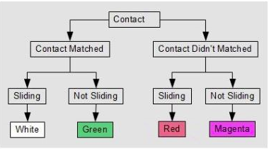
As can be seen in the image above, contacts are separately into two groups:
- Contact matched: In this case, contacts were present in a previous step (e.g., a box or set of vehicle wheels touching the ground) and are located in the same place as in that previous step. Note that contact matching is only performed when the Slip Displacement option is enabled.
- Contact non-matched: In this case, a new contact is made (e.g., a box falls and hits the ground), or the Slip Displacement option is not enabled.
Within each category, you can have sliding contact (i.e., a dynamic, moving contact with kinetic friction) or a non-sliding contact (i.e., static friction).
Pressing ALT+C cycles the contact types according to the following sequence:
- Contact Force: Green
- Contact Torque: Blue
- Contact Penetration: Yellow
- Contact Direction: Cyan
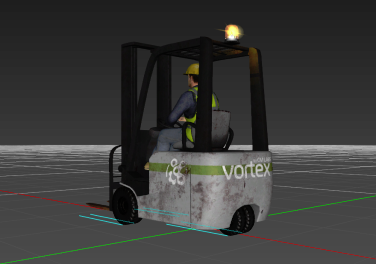
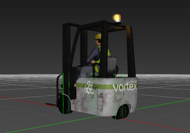
|
|
| Example of contact direction lines (left) and contact force lines (right) | |
It is possible to change the scaling of the lines, to provide better readability, with the following commands:
- ALT+X: Halves the length of the lines in the contact display
- ALT+Z: Doubles the length of the lines in the contact display