Assemblies
 An assembly contains the basic objects for dynamic simulation: parts, constraints and graphics. It is built and used by mechanical engineers and contains all that is necessary to implement the mechanical design of a component. It is a object that reacts to mechanical and data inputs. The Assembly can be added to a scene or to a mechanism.
Assemblies can also contain nested assemblies, which are then referred to as sub-assemblies for clarity.
Assemblies simplify the creation of mechanisms such as vehicles, cranes, or robots. You can transform an entire assembly, or rotate it to view it in a different perspective.
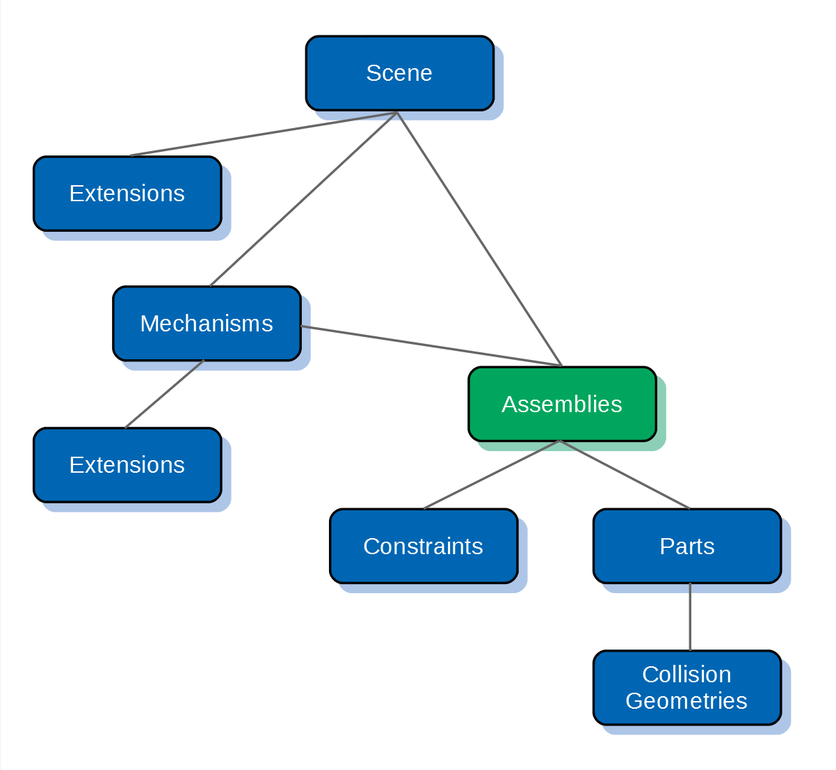
The figure below indicates where assemblies are located in the Vortex® Studio hierarchy.
An assembly consists of parts and their collision geometries, constraints, and attachment points but can also include other objects such as dynamics extensions, scripts, Linking interfaces and graphics.
Building Assemblies from a Graphics Gallery or a 3D Model
Given a graphic asset, or 3D reference model, Vortex® can generate the dynamics components (parts and collision geometries) to match.
- If you are not already in the Assembly editor, either open an existing assembly or create a new one.
This assembly will hold the parts built from the graphic asset (to be imported in the next steps). - Do one of the following:
- Insert 3D models through a Graphics Gallery (recommended).
- In the Toolbox, double-click 3D Model....
- In the Toolbox, double-click Galleries From Files.
For b., the Import 3D Models panel appears.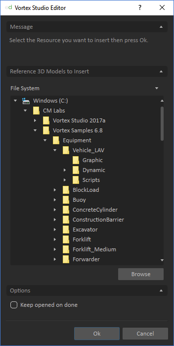
- Do one of the following:
- Find the 3D model file you want to use under the File System section and double-click it.
- Click the Browse button under the File System tree and double-click the 3D model file you want to use.
Valid asset file formats include *.flt, *.osg, *.ive, and *.cive.
For a complete list of formats, have a look at the complete list of supported 3d model formats..
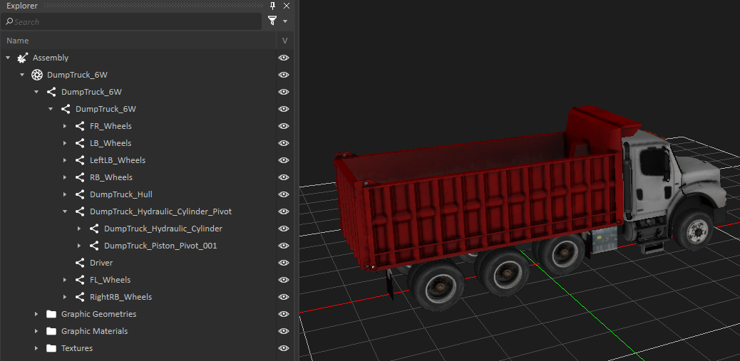
The Vortex Editor imports the 3D model file into a new Graphics Gallery. The Graphics Gallery appears in the 3D View and you can now find the node tree for the model under the Explorer Panel
For c., the Add Graphics Gallery panel appears.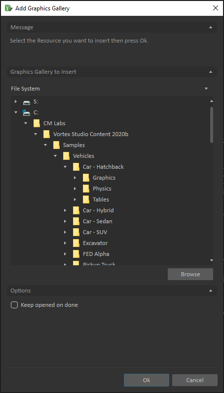
- Do one of the following:
- Find the graphics gallery file you want to use under the File System section and double-click it.
- Click the Browse button under the File System tree and double-click the graphics gallery file you want to use.
- Once the Graphic Gallery is shown and the node tree is in the Explorer panel, you can create parts. For each part you want to create, follow the instructions under Building Parts from a 3D Model.
When you are finished creating parts, save the Assembly.
If the graphic file is not found, no graphic will be loaded. An error might occur during runtime simulation causing the simulation to not run properly
Creating Assemblies and Adding Parts Manually
Creating assemblies and parts from a 3D model is by far the best option; however, sometimes you need to create assemblies and add parts to them manually.
In this case, you can follow the instructions in this section.
- If you are not already in the Assembly editor, either open an existing assembly or create a new one.
- Follow the instructions in Creating Parts and Geometries Manually
Working with Linking Interfaces
Similar to the Vortex® High Level (VHL) Interface for mechanism, the Linking Interface exposes a defined subset of the assembly's internal fields as inputs, outputs and parameters. It also exposes some dynamics related fields required to be able to create a successful linking between two Assemblies using the Assembly Link.
The values of the Linking Interface are exposed so that a systems integrator can modify these values without knowledge of the internal complexity of the Assembly. Additionally, non-modifiable properties and their respective values and parameters are protected during modification, testing, and validation stages.
Linking Interface properties are accessible in the Assembly and Mechanism documents, but they can only be created in the Assembly editor.
Linking Interface properties includes:
- Inputs: These are properties used to operate the Assembly during simulation.
- Outputs: These are properties used to get and read information about the outcomes of the simulation.
- Parameters: These are the properties that define or specify Assembly behavior or used to control and condition the way an Assembly is simulated. They are typically agreed upon and provided at the design stage of the development of a given Assembly.
Also, a Linking Interface includes additional fields that are required to properly link two Assemblies using the Assembly Link.
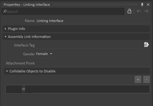
- Interface Tag: An empty interface tag will always allow linking. If specified, linking between two assemblies will only be possible if their Linking Interface's tag matches.
- Gender: This field indicates whether the interface is either Female (default) or Male, and is analogous to physical plugs. When an Assembly Link's Only connect Male-Female parameter is set to True, it will only allow linking a male Linking Interface with a female Linking Interface.
- Attachment Point: This field represents the Attachment Point that will be used to create an Attachment between the Assemblies. No connection can occur if the field is empty or invalid. This field is necessary so that an Assembly Link extension can create the physical connection. More information about this feature can be found on the Assembly Link page.
- Collidable Objects to Disable: When two Linking Interfaces from different assemblies are linked together, all collidable objects specified in this list won't collide with collidable objects defined in the other LinkingInterface.
Creating a New Linking Interface
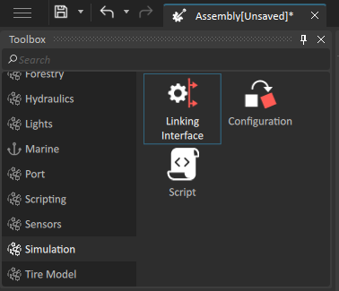
To create a Linking Interface, you must first open the Assembly editor. The extension can be found inside the Simulation section of the Toolbox. To create a new instance, either double-click on the Linking Interface icon or drag it into the 3D View window or the explorer tree.
Expose object's properties
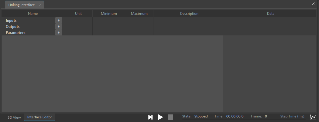
The Linking Interface Editor allows you to expose objects' properties in the Linking Interface. You can also use it to rename properties, change minmum and maximum values and add meaningful descriptions for each property.
- After creating a Linking Interface from the Toolbox, the Linking Interface Editor should open. If it was closed, double-click on the Linking Interface item from the Explorer tree to open its Linking Interface Editor page.
- In the Explorer tree, select an object that you want to expose its properties. The selected object's properties are shown in the property panel on the right.
From the Property panel, drag and drop the property you want to expose onto either the Input, Output, or Parameters section of the Interface Editor. It creates a Linking Interface property and maps the property to the object's exposed property.
Read-only input and parameter properties cannot be exposed in the Linking Interface Editor.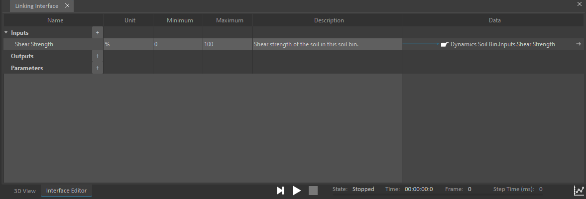
- Now you can perform any of these tasks to customize your Linking Interface property:
- By default, the Linking Interface property uses the name of the object's exposed property. To use a different name, double-click on the Name cell and type the new name.
- To add a description for the Linking Interface property, double-click on the Description cell and type the description. You can press the Enter or Tab key to finish editing.
- To enter minimum and maximum values for the Linking Interface property, double-click on the appropriate Minimum and Maximum cells, enter the values and press the Enter or Tab key. Only property of double or integer type supports min and max values.
- To break the map between the Linking Interface property and the object's exposed property, hover over the arrow in the Data column of the Linking Interface property you want to unmap, a trash can icon appears, click on it. The property still appears in the Linking Interface Editor, but the map to the object's property has been unmapped.

- To map an object's property to an existing Linking Interface property, drag and drop the object's property onto the Data column of the Linking Interface property's row. An existing Linking Interface property can be mapped to multiple properties of the same object or different objects.
- To delete an entire Linking Interface property from the Linking Interface, select the row you want to delete then press the Delete key.
Create Linking Interface properties
Additionally, you can add Inputs, Outputs and Parameters properties to the Linking Interface editor by clicking the + button next to Container heading.
Clicking the + button prompts a drop-down list, select the type of data for this new output (e.g., Integer, Boolean, String etc.). A property of the selected data type is created and inserted at the end of the container, where you can edit its details.
The feature allows you to create and organize Linking Interface properties in advance. You can group the properties using containers. The organized properties can then be mapped to objects' properties via drag and drop.
Property Panel of a Linking Interface
In addition to the Linking Interface editor, selecting a Linking Interface from the Explorer Tree will display its properties in the Properties Panel. These properties are needed in order to create a valid link between two Linking Interfaces.
Editing a Linking Interface
This procedure explains how to load an existing interface in the Linking Interface Editor.
- If you are not already in the Assembly editor, open the assembly containing the Linking Interface since it can only be modified there.
- From the Explorer panel, open the Linking Interface you want to open.
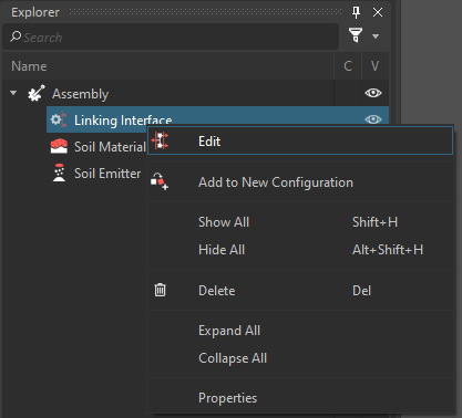
Right-click the Linking Interface item in the explorer tree and select Edit from the context menu to open the Linking Interface Editor in the main window. Double-click the Interface will also work.
Each Linking target can only be bound to a single property.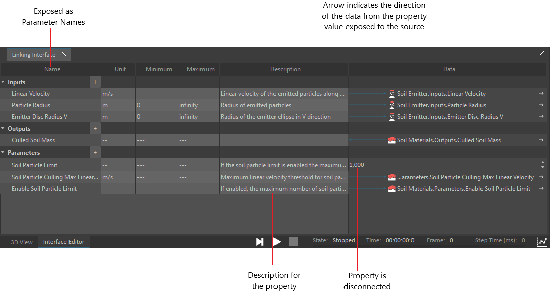
- To undock the Interface Editor, right-click anywhere on it and select Undock. This allows you to see the contents of the 3D View and the Interface Editor at the same time and move it around the workspace. To dock it again, right-click inside the Interface Editor window and click Dock.
What You Can Do With Assemblies
Once you have an assembly you may perform any of the following tasks:
- Modify the position and orientation of parts
- Set the initial dynamic state of the parts in the assembly
- Set the threshold values for auto-sleep to optimize performance during simulation
- Set the auto-merge thresholds of parts in the assembly
- Add and configure the constraints
- Define attachment points on this assembly