Linking Interface
- DEVOPS
Working with Linking Interfaces
Similar to the Vortex® High Level (VHL) Interface for mechanism, the Linking Interface exposes a defined subset of the assembly's internal fields as inputs, outputs and parameters. It also exposes some dynamics related fields required to be able to create a successful linking between two Assemblies using the Assembly Link.
The values of the Linking Interface are exposed so that a systems integrator can modify these values without knowledge of the internal complexity of the Assembly. Additionally, non-modifiable properties and their respective values and parameters are protected during modification, testing, and validation stages.
Linking Interface properties are accessible in the Assembly and Mechanism documents, but they can only be created in the Assembly editor.
Linking Interface properties includes:
- Inputs: These are properties used to operate the Assembly during simulation.
- Outputs: These are properties used to get and read information about the outcomes of the simulation.
- Parameters: These are the properties that define or specify Assembly behavior or used to control and condition the way an Assembly is simulated. They are typically agreed upon and provided at the design stage of the development of a given Assembly.
Also, a Linking Interface includes additional fields that are required to properly link two Assemblies using the Assembly Link.
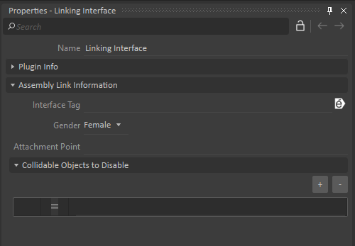
- Interface Tag: An empty interface tag will always allow linking. If specified, linking between two assemblies will only be possible if their Linking Interface's tag matches.
- Gender: This field indicates whether the interface is either Female (default) or Male, and is analogous to physical plugs. When an Assembly Link's Only connect Male-Female parameter is set to True, it will only allow linking a male Linking Interface with a female Linking Interface.
- Attachment Point: This field represents the Attachment Point that will be used to create an Attachment between the Assemblies. No connection can occur if the field is empty or invalid. This field is necessary so that an Assembly Link extension can create the physical connection. More information about this feature can be found on the Assembly Link page.
- Collidable Objects to Disable: When two Linking Interfaces from different assemblies are linked together, all collidable objects specified in this list won't collide with collidable objects defined in the other LinkingInterface.
Creating a New Linking Interface
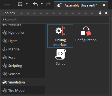
To create a Linking Interface, you must first open the Assembly editor. The extension can be found inside the Simulation section of the Toolbox. To create a new instance, either double-click on the Linking Interface icon or drag it into the 3D View window or the explorer tree.
Expose object's properties
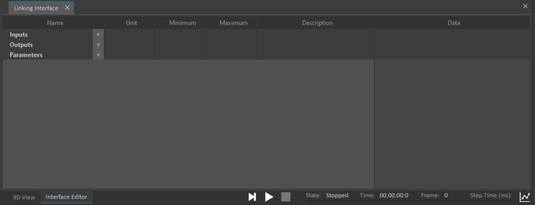
The Linking Interface Editor allows you to expose objects' properties in the Linking Interface. You can also use it to rename properties, change minimum and maximum values and add meaningful descriptions for each property.
- After creating a Linking Interface from the Toolbox, the Linking Interface Editor should open. If it was closed, double-click on the Linking Interface item from the Explorer tree to open its Linking Interface Editor page.
- In the Explorer tree, select an object that you want to expose its properties. The selected object's properties are shown in the property panel on the right.
From the Property panel, drag and drop the property you want to expose onto either the Input, Output, or Parameters section of the Interface Editor. It creates a Linking Interface property and maps the property to the object's exposed property.
Read-only input and parameter properties cannot be exposed in the Linking Interface Editor.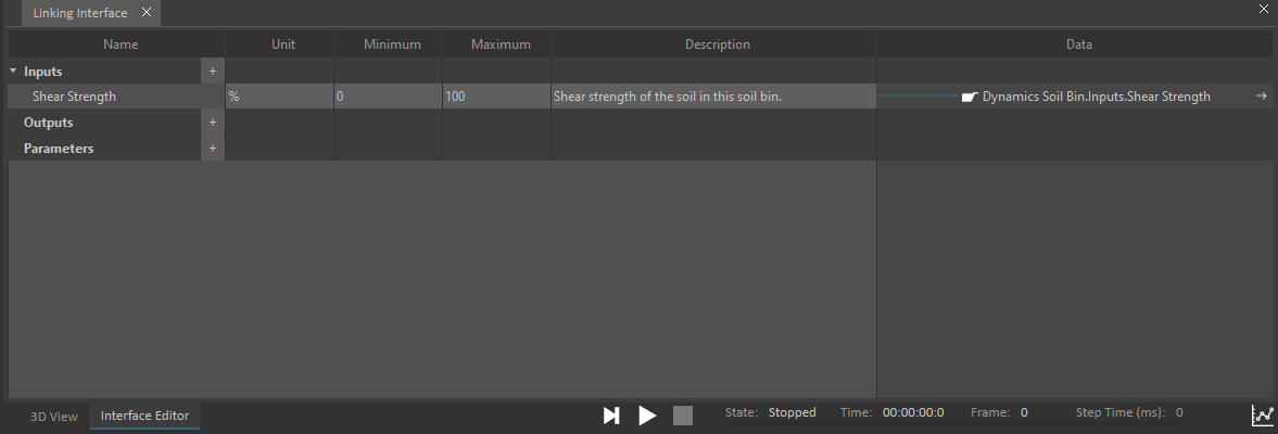
- Now you can perform any of these tasks to customize your Linking Interface property:
- By default, the Linking Interface property uses the name of the object's exposed property. To use a different name, double-click on the Name cell and type the new name.
- To add a description for the Linking Interface property, double-click on the Description cell and type the description. You can press the Enter or Tab key to finish editing.
- To enter minimum and maximum values for the Linking Interface property, double-click on the appropriate Minimum and Maximum cells, enter the values and press the Enter or Tab key. Only property of double or integer type supports min and max values.
- To break the map between the Linking Interface property and the object's exposed property, hover over the arrow in the Data column of the Linking Interface property you want to unmap, a trash can icon appears, click on it. The property still appears in the Linking Interface Editor, but the map to the object's property has been unmapped.

- To map an object's property to an existing Linking Interface property, drag and drop the object's property onto the Data column of the Linking Interface property's row. An existing Linking Interface property can be mapped to multiple properties of the same object or different objects.
- To delete an entire Linking Interface property from the Linking Interface, select the row you want to delete then press the Delete key.
Create Linking Interface properties
Additionally, you can add Inputs, Outputs and Parameters properties to the Linking Interface editor by clicking the + button next to Container heading.
Clicking the + button prompts a drop-down list, select the type of data for this new output (e.g., Integer, Boolean, String etc.). A property of the selected data type is created and inserted at the end of the container, where you can edit its details.
The feature allows you to create and organize Linking Interface properties in advance. You can group the properties using containers. The organized properties can then be mapped to objects' properties via drag and drop.
Pass Through fields
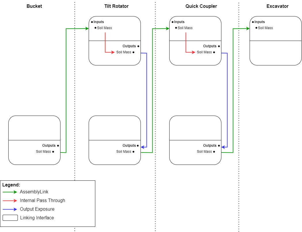
Pass Through fields allow to easily transfer values through the Linking interfaces of a chain of Assembly links. To achieve that, Pass Through fields instantly communicate their values inside a Linking interface, whenever that value changes.
A typical example is the transfer of the mass of soil contained in a bucket assembly all the way to the excavator assembly, through two intermediate assemblies. The soil mass value needs to be transferred from the bucket assembly to the tilt rotator assembly, and then to the quick coupler assembly, and finally to the excavator assembly. This value does not need to be processed, just transferred from one assembly to the other, as quickly as possible.
Setting up Pass Through fields
Two fields can "Pass Through" their value if and only if they meet all of the following conditions:
- one field is an input and the other is an output
- they have the same name
- they have the same type
- they are in the same Linking interface
- they are set as Pass Through.
When that happens, the Pass Through mechanism is automatically triggered and the input value will automatically be transferred to the output, with no delay. From then on, the output value will instantly change upon change of the input value.
To set up Pass Through fields, one has to check the box in the Pass Through column for each of the two fields.
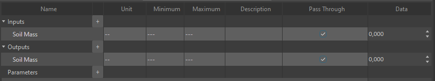
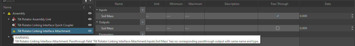
It is important to note that the user is responsible for properly setting corresponding Pass Through fields. For example, checking the Pass Through checkbox for a field without doing the same for a corresponding field will trigger a Warning in the Assembly. A Warning will also be triggered if two fields are checked but do not meet all the conditions above (same name, same type, etc...)
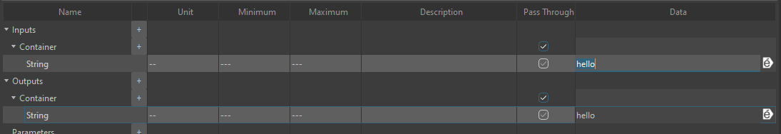
Input containers and output containers can also be Pass Through. When a container is set as Pass Through, all children nodes are considered Pass Through, and all subfields' checkboxes are set as checked, are greyed out, and cannot be unchecked. Note that the user is responsible for the exact correspondance of the subfields of two corresponding Pass Through containers. Any difference in the subpath, or type between two subfields will prevent the Pass Through mechanism to work as expected on those subfields.
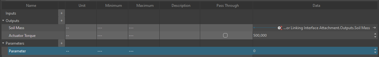
Parameter fields and fields that expose other fields are not allowed to be Pass Through, and as such, will not display the checkbox in the Pass Through column.
Property Panel of a Linking Interface
In addition to the Linking Interface editor, selecting a Linking Interface from the Explorer Tree will display its properties in the Properties Panel. These properties are needed in order to create a valid link between two Linking Interfaces.
Editing a Linking Interface
This procedure explains how to load an existing interface in the Linking Interface Editor.
- If you are not already in the Assembly editor, open the assembly containing the Linking Interface since it can only be modified there.
- From the Explorer panel, open the Linking Interface you want to open.
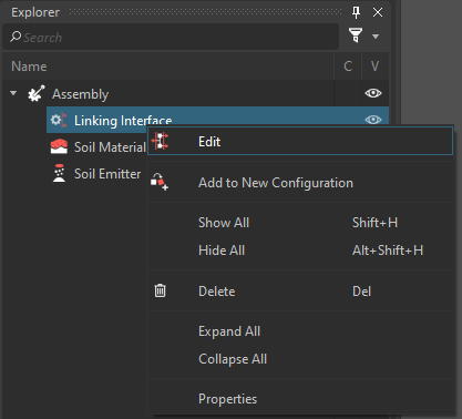
Right-click the Linking Interface item in the explorer tree and select Edit from the context menu to open the Linking Interface Editor in the main window. Double-click the Interface will also work.
Each Linking target can only be bound to a single property.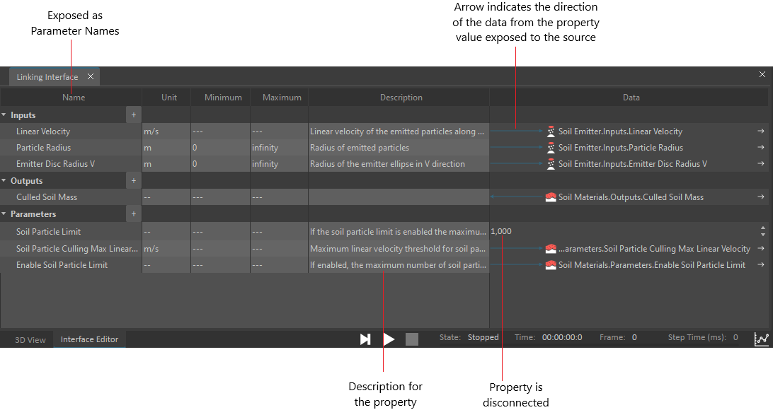
- To undock the Interface Editor, right-click anywhere on it and select Undock. This allows you to see the contents of the 3D View and the Interface Editor at the same time and move it around the workspace. To dock it again, right-click inside the Interface Editor window and click Dock.