Maritime Tutorial 2 : Creating a Vessel Mechanism
In this training pack, we will go over key concepts and guidelines to get you started with nautical simulations in Vortex® Studio.
This module focuses on using Vortex Studio to create a working vessel mechanism to be used in the offshore scene created in Module 1.
Prerequisites
You need to have Vortex® Studio and the Vortex Studio Demo Scenes installed to be able to follow all steps in this tutorial.
1. Creating a New Mechanism and Importing Graphics
- Click on the top-left button in Vortex Studio Editor interface (the button with 3 horizontal bars) to go to the Home Page.
Click on Mechanism to create a new mechanism file.
Similar to creating a new scene, creating a new mechanism opens an empty document. However, the mechanism additionally has a grid that will be useful when modeling.
- Change the name of the Mechanism to Vessel in the Explorer window.
- Click on the Graphics section of the Toolbox and double-click on Galleries from Files...
Navigate to the ...\Vortex Studio Content <VERSION>\Demo Scenes\Equipment\Normand_Kraken\Graphic directory, select NormandKraken_Normand_Kraken.vxgraphicgallery and click on Open.
For this tutorial, we are using a 3D model that has already been converted to a Vortex Studio graphic gallery format (the .vxgraphicgallery format). To use a new 3D model for the vessel, you could have double-clicked on the 3D Models... object in the Graphics section of the toolbox instead. This would have allowed you to select a 3D in one of the Vortex Studio supported file formats (Filmbox - FBX, Collada - DAE, OpenSceneGraph - IVE, CIVE) and load it in Vortex Studio. In that scenario, a Vortex Studio graphics gallery would have been automatically created.
- Use the middle-mouse button and scroll wheel to look around the 3D model. You will notice that the bottom of the hull is aligned with the grid.
Go to the Basics section of the Toolbox and double-click on Empty Assembly.
The Assembly is a container for all of the parts that will make up a mechanism.
- Save your new mechanism file in your working directory.
Building the Vessel Assembly and Parts
- In the Explorer, expand the Gallery node and click on the top graphic node of the Normand Kraken graphic gallery (Normand_Kraken).
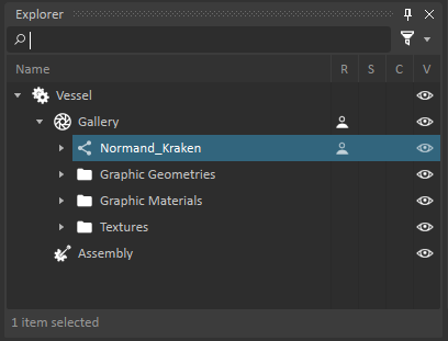
- Right-click on the node and select the Create Part In Assembly menu item. You will see a new part appear under the Assembly section of the mechanism.
- Save the mechanism file
- Double-click on the Assembly to edit that specific element.
- Right-click on the Normand_Kraken part and select the Create Best-Fit Geometry > Convex Mesh... menu option.
- Set the Excluded Graphic Nodes fields to LARS_Base_DOF|LARS_Base_Outer_Hydraulic_Cylinder_DOF.
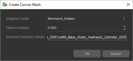
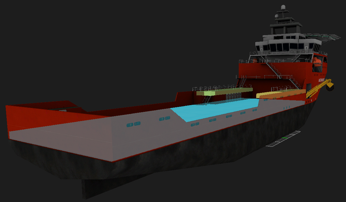
- Leave the other options with their default values in the Create Convex Mesh dialog and click on OK to create a collision volume for the vessel, excluding the LARS crane attached on its right side.
- Click on the Eye icon next to the newly created Convex Mesh to hide it.
- In the Toolbox, double-click on Box in the Collision Geometries section.
- Use the movement and scale tools to size the box to cover the deck of the vessel and have the top of the box line up with the deck surface. This box will be used to be able to place objects on the ship deck.
- Set the Material of the box to Ground.
- Use the Ctrl-D key combination to make a copy of the existing box, then resize it to cover one of the two elevated decks at the front of the vessel.
- Use Ctrl-D once again to make a copy of smaller box and move it to cover the second elevated deck.
- Save the Vessel mechanism.
- Rename the convex mesh to Buoyancy.
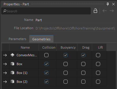
- Click on the top Part node in the Explorer window.
- Click on the Geometries tab in the Properties dialog.
- Make sure that only Collision is checked for the boxes, while Buoyancy and Drag are checked for the Buoyancy convex mesh geometry.
- While still selecting the top-level Part, go to the Parameters tab and set the Mass to 5,500,000.00 kg.
- Push the button to automatically Compute the Inertia and COM.
- Right click on eye icon next to Part in Explorer tree and select Inertia.
- Use the inertia movement, rotation and scale controls at the top of the 3D view to tilt the inertia to be horizontal and scale the tensor to be larger than the vessel.
- Select the Box convex meshes one by one and make sure that they are set to be Enabled. Also make sure that Buoyancy Enabled and Drag Enabled are not checked.
- Select the Buoyancy convex mesh and check the Buoyancy Enabled and Drag Enabled checkboxes.
- Set the Center of Buoyancy to 0.0, 0.0, 5.0.
- Set the Displaced Volume to 23,000.00 m3.
Set the Drag Coefficient to 2.0, 2.0, 40.0.
You may need to tweak the values of the displaced volume or increase the scale of your inertia tensor if the vessel does not float properly in later steps.
- Save the assembly and mechanism.
Adding the Vessel to the Scene
- Go back to the scene editing tab and add your new Vessel mechanism as seen in Part 1 of the Maritime tutorial. You should be able to select the Vessel from your list of Opened Resources if the file is still open in the Editor.
Run the simulation.
Your vessel should float. If it sinks a bit, adjust values for Displaced Volume and / or Center of Buoyancy and / or Part Inertia Tensor. You will likely notice that water can be seen over the deck at the back of the vessel when the deck goes below the waterline even if the side of the vessel do not dip below water. This is a visual anomaly that can be corrected with a tool called the Imposter tool.
- Save your scene and switch back to the vessel mechanism tab.
- Press the Shift-G key combination on your keyboard to hide the collision geometries from the 3D view.
Go to the Marine section of the Toolbox and double-click on Imposter to add an importer object.
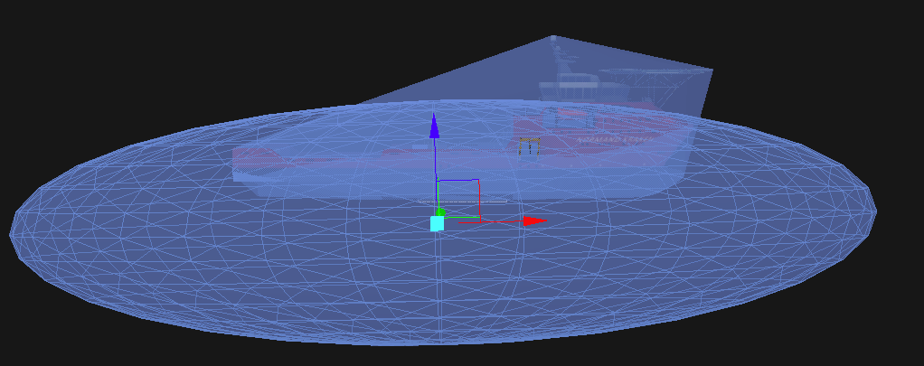
By default, the imposter object is very small and is hidden inside of the vessel 3D model. We will need to move and scale it.
- Select the Imposter object in the Explorer window.
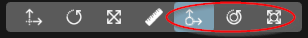
- Click the directional movement button at the top of the 3D view to activate the object movement mode.

- Move the Imposter object up above the vessel to see it.
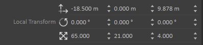
- Set the scale of the Imposter object to 65.0, 21.0, 4.0 in its local transform.
- Set the position of the Imposter object to -18.5, 0.0, 9.8 in its local transform.
Go to the Basics section of the Toolbox and double-click on Connection Container.
The Connection Container allows the user to create connections between objects so that data can flow between them as the simulation runs. We will use it to link the position of the Imposter to the position of the vessel so that it always stays with it as the vessel moves.
- Select the Imposter object in the Explorer window.
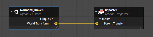
- Drag-and-drop the Parent Transform input property of the object to the Connections Editor.
- Select the Normand_Kraken part in the Explorer Window.
- Drag-and-drop the World Transform output property of the objects to the Connections Editor.
- Draw a link between the two circles to join them.
- Save the mechanism.
- Run the simulation and confirm that no water gets on the ship deck.
Adding a Thruster
Now that the vessel floats, we will now make it move with the help of a thruster.
- Go back to the Vessel mechanism tab in the Vortex Studio Editor.
- Double-click on the vessel's Assembly to edit it.
- Use the Shift-G key combination to hide collision volumes. You can also hide the Inertia volume by right-clicking on the eye next to the Normand_Kraken part and unchecking the Inertia option.
- Right-click on the Normand_Kraken part in the Explorer window and select Insert Attachment Point.
- Rename the new attachment point to Thruster AP.
- Set the Local Transform for the new attachment point to -51.0, 0.0, 2.1.
- Save the assembly.
Go back to the vessel mechanism tab of the editor.
You will now see a white sphere appear where the attachment point was created.
- Go to the Marine section of the Toolbox and double-click on Thruster.
- Select the Thruster in the Explorer window.
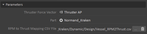
- In the Parameters section, click on the button with three vertical dots at the end of the Thruster Force Vector field, then press the Browse button (...) in the sub-menu that opens.
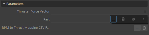
- Expand the Assembly and Part in the Explorer window to select the Thruster AP attachment point created earlier.
- Click on the three vertical dots button at the end of the Part field, then press the Browse button and pick the Normand_Kraken part under the Assembly.
- Click on the Browse button (...) at the end of the RPM to Thrust Mapping CSV File field and navigate to the ...\Vortex Studio Content <VERSION>\Demo Scenes\Equipment\Normand_Kraken\Dynamic\Design directory, then pick the Vessel_RPM2Thrust.csv file and click on Open.
- Set the Current RPM Input property to 1,500.00.
- Save your mechanism.
- Go back to the scene and Run the simulation.
You should now see the vessel start moving forward. Based on the assigned RPM, the thruster system will calculate an amount of thrust and generate that thrust in the simulation to make the vessel start moving forward. When creating the thruster, we associated it with the vessel part as well as with the attachment point that we created earlier. While the part indicates the part that the thrust force will be associated, the attachment point is a vector that indicates the directional of the force. If we had wanted a side thruster, we could have rotated the attachment point in the assembly. If we wanted the thruster to be directional, we could attached to a part that moves in our vessel, using a hinge or other constraint.
Adding Wake Visual Effects
- Edit your vessel's assembly.
- Right-click on the Normand_Kraken part and select the menu option to Insert Attachment Point.
- Rename the attachment point to "Front Vessel".
- Set the Local Transform of the new attachment point to 46.0, 0.0, 2.1.
- Save the assembly.
- Go back to the vessel mechanism tab.
- Go to the Marine section of the Toolbox and double-click on Wake Effect.
- If you closed it before, double-click on the Connections Container to bring back the Connections Editor.
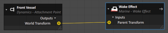
- Click on the Wake Effect object in the Explorer window.
- Click-and-drag the Parent Transform input property to the Connections Editor.
- Click-and-drag the World Transform output property of the Front Vessel attachment point to the Connections Editor.
- Draw a connection between the two new elements that were added to the Connections Editor.
- Set the input properties for the Wake Effect as follows:
- Speed = 4.0 m/s
- Generation Width = 1.5 m
- Width = 10.0 m
- Lifetime = 120.0 s
- Intensity = 0.040
- Particle Radius = 30.0 m
- Length = 50.0 m
- Rotation Range = 0.0, 0.0
- Set the Particle Limit parameter to 180
- Set the Local Transform rotation properties to 0.0, 0.0, 90.0
- Save the mechanism.
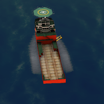
- Run the simulation and you will now see that a wake effect is rendered in the 3D view as the vessel advances on either side of the hull.
- In the mechanism editor tab, go to the Marine section of the Toolbox and double-click on Ocean Wake.
- Go to the Connections Editor for the mechanism.
- Drag-and-drop the Parent Transform input property of the Ocean Wake object to the connection editor.
- Draw a connection between the existing World Transform property of the Normand_Kraken part and Parent Transform property of the Ocean Wake.
- Configure the Ocean Wake as follows:
- Width = 15.0 m
- Length = 100.0 m
- Draft = 5.0 m
- Kelvin wave form scale = 2.0
- Kelvin wave minimum amplitude = 0.0
- Kelvin wave maximum amplitude = 0.05
- Kelvin wave scale = 8.0
- Save the mechanism.
- Run the simulation and you will now see that a wake effect is behind the hull of the vessel as it moves forward.