Maritime Tutorial 3 : Building an Offshore Crane
In this training pack, we will go over key concepts and guidelines to get you started with nautical simulations in Vortex® Studio.
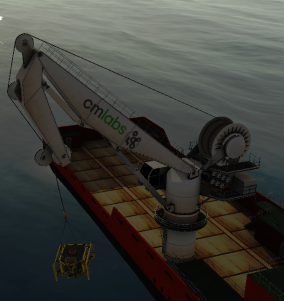
This module focuses on using Vortex Studio to create a working offshore crane, that can be attached to the vessel created in Module 2.
Prerequisites
You need to have Vortex® Studio and the Vortex Studio Demo Scenes installed to be able to follow all steps in this tutorial.
Creating a New Mechanism with Parts
- Go to the top-level Vortex Studio menu and create a new mechanism.
- Change the name of the new mechanism to "OffshoreCrane".
- Save the new mechanism in your course assets.
- Go to the Graphics section of the Toolbox and double-click on Galleries from files...
- Browse to the ...\Vortex Studio Content <VERSION>\Demo Scenes\Equipment\OffshoreCrane\Hydramarine\Graphic folder and select the Hydramarine_KnucleBoom_Heave_Comp_Hydramarine.vxgraphicgallery file.
- Create an empty Assembly.
- Rename the Assembly to "Crane".
Create Parts in the new assembly from the following nodes in the crane graphic galleries, with the associated properties and collision geometries. You can use the button to automatically compute COM and inertia tensor for all parts, but only after you've created the collision geometries for parts that have them.
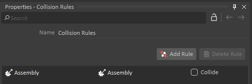
Node Name Mass (kg) Collision Geometry Material Hydramarine_Base_Geometry 17000.0 Two cylinders (Manual creation, not automatic with best-fit) Steel Hydramarine_Turret 20000.0 None N/A Hydramarine_Turret_Drum 20000.0 Cylinder Steel Hydramarine_Arm 19500.0 Box (Along top of geometry) Steel Hydramarine_Elbow 14000.0 Box (Along top of geometry) Steel Hydramarine_Turret_Outer_Piston 500.0 None N/A Hydramarine_Arm_Inner_Piston 500.0 None N/A Hydramarine_Arm_Outer_Piston 500.0 None N/A Hydramarine_Elbow_Inner_Piston 500.0 None N/A Hydramarine_Elbow_Wheel_001 200.0 Cylinder Steel Hydramarine_Elbow_Wheel_002 200.0 Cylinder Steel Hydramarine_Elbow_Wheel_003 200.0 Cylinder Steel Hydramarine_Elbow_Wheel_004 200.0 Cylinder Steel - Go to the Basics section of the Toolbox and add a Collision Rules object to the assembly.
- Click on Add Rule and select the Assembly in the first two columns of the Collision Rules object.
- Leave the Collide box unchecked.
- Save the mechanism.
Establishing Constraints Between Parts
Select the Hydramarine_Base_Geometry part and set its Control property to Static under the Inputs tab.
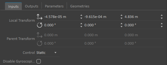
The Static dynamic property will allow us to easily test our offshore crane as we build it. Without this property, the crane would fall over in the mechanism editor and could only be tested properly by adding it to a scene and going back-and-forth between the mechanism editor and the scene editor. We just need to remember to set the Control back to Dynamic when we are satisfied with the functionality of our crane.
While still at the assembly level, create Constraints between the following parts, with the following axes, limits and control methods. You should always select the two parts involved in each constraint in the order that they are listed, holding down the Ctrl key to select both, then clicking on the constraint type in the Toolbox. The next steps will show how to create the first constraint and can be repeated to create the remaining constraints.
Constraint SpecificationsFirst Part Second Part Constraint Type Primary Axis Secondary Axis Control Limits Hydramarine_Turret Hydramarine_Base_Geometry Hinge Z+ Y+ Locked None Hydramarine_Turret_Drum Hydramarine_Turret Hinge Y+ Z+ Locked None Hydramarine_Arm Hydramarine_Turret Hinge Y+ Z+ Free None Hydramarine_Elbow Hydramarine_Arm Hinge Y+ Z+ Free None Hydramarine_Elbow_Wheel_001 Hydramarine_Elbow Hinge Y+ Z+ Free None Hydramarine_Elbow_Wheel_002 Hydramarine_Elbow Hinge Y+ Z+ Free None Hydramarine_Elbow_Wheel_003 Hydramarine_Elbow Hinge Y+ Z+ Free None Hydramarine_Elbow_Wheel_004 Hydramarine_Elbow Hinge Y+ Z+ Free None Hydramarine_Turret_Outer_Piston Hydramarine_Turret Hinge Y+ Z+ Free None Hydramarine_Arm_Inner_Piston Hydramarine_Arm Hinge Y+ Z+ Free None Hydramarine_Arm_Outer_Piston Hydramarine_Arm Hinge Y+ Z+ Free None Hydramarine_Elbow_Inner_Piston Hydramarine_Elbow Hinge Y+ Z+ Free None Hydramarine_Turret_Outer_Piston Hydramarine_Arm_Inner_Piston Cylindrical X- Y+ Locked Position Upper Limit : 4.8 m
Hydramarine_Elbow_Inner_Piston Hydramarine_Arm_Outer_Piston Cylindrical X- Y+ Locked Position Upper Limit : 3.7 m - In the Explorer window, select the Hydramarine_Turret.
- Hold down the Ctrl key and select the Hydramarine_Base_Geometry part.
- Go to the Basic Constraints section of the Toolbox and double-click on Hinge.
Select the newly created constraint in the Explorer.
The name that is automatically generated for new constraints contains the name of the two selected parts, separated by an abbreviation of the constraints type in square brackets.
- Go to the Part 1 Offset section of the Attachments tab of the Inputs tab and click on the axis button at the end of the Primary Axis field.
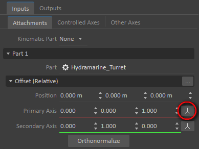
- Select the Z+ axis.
- Click on the axis button next to the Secondary Axis field and select the Y+ axis.
- In the Part 2 section, click on the Browse (...) button next to the Offset (Relative) heading.

- In the dialog that opens, click on the Apply button and close the dialog with the OK button.
- Click on the Controlled Axes tab of the Inputs tab and set the Control type as required.
- If any limits are required, check the box next to the Limits section, then expand it and set the limits as indicated.
Repeat for all remaining constraints.
As you build out your constraints, you can always run the simulation at any time to see how all parts are holding together, or not. You can also test the movement of constraints by either using the spring test tool in the editor, or by specifying values for the Lock Velocity property of any of the locked constraints.
- Save the crane assembly.
Adding Hook Assembly
- Go back to editing the crane mechanism and Insert the Graphic Gallery for the crane hook, which can be found under the TrainingAssets\OffshoreCrane directory, called Hydramarine_KnucleBoom_Heave_Comp_Platform_KnuckleBoom_Hook.vxgraphicgallery.
- Position the hook under the crane, above the mechanism editor grid.
- Create a new Empty Assembly in the mechanism and name it Hook.
- Create a Part in the Hook assembly from the hook using the top-level Platform_KnuckleBoom_Hook node from the newly imported gallery.
- Select the Part and add a cylinder collision geometry to it.
- Edit the Hook assembly.
- Set the Part Mass to 100.00 kg.
- Click the Compute Inertia and COM button.
- Set the cylinder collision geometry material to Steel.
- Right-click on the hook part and create a new Attachment Point.
- Move the point so that it is located towards the bottom of the hook.
- Name the point "Hook AP".
- Save all open files.
Creating the Cable System
- Back at the mechanism level, select the Cable Systems section of the Toolbox and double-click on the Generic Cable item.
- Leave all values under the Dynamic Properties sub-section of the Generic Cable to their default values, except for Cable Diameter which should be set to 0.05m.
- Select the Dynamics General Cable node, under Generic Cable.
- Expand the Definition section of Dynamics General Cable, found under the node Parameters in the Properties editor, then expand the Point Definitions section.
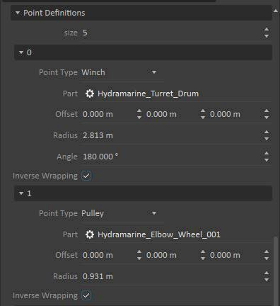
Set the size of Point Definitions to 5.
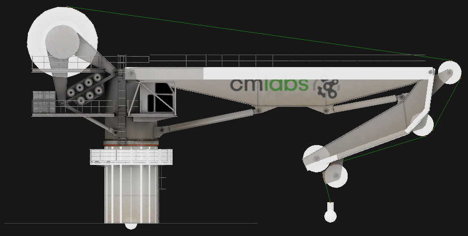
The size of the Point Definitions array is determined by the number of touch points where the cable interacts with the crane mechanism. In the case of this crane, the cable will start with the main drum at the back of the crane (1). It then touches three pullies (2 - 3 - 4) and eventually connects to the top of the hook block (5). it is not necessary to include the fourth pulley in the system as the cable will only rest on it.
- For the first Point Definition (0), set the Point Type to Winch.
Click on the three vertical buttons at the end of the Part field, then on the button with three horizontal dots. Select the Hydramarine_Turret_Drum part, either in the list of parts in the Explorer window, or visually in the 3D editor view to assign it to this point definition.
As you select a part for the point definition, Vortex Studio will analyze the part and extract data to complete the Offset, Radius and Angle fields of the Point Definition. Vortex Studio expects the part selected as the winch to be part of a hinge constraint.
- Change the Radius to 2.3m, since the cylinder that was automatically created for the drum part considers the edges of the drum as being part of it's radius.
- Expand the second Point Definition (1), set its Point Type to Pulley and select the Hydramarine_Elbow_Wheel_001 part.
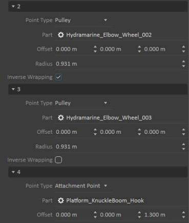
- Configure the third and fourth Point Definitions (2 and 3) as Pulleys, using parts Hydramarine_Elbow_Wheel_002 and Hydramarine_Elbow_Wheel_003.
- Set the last Point Definition (4) Point Type to Attachment Point, and select the Platform_KnuckleBoom_Hook part created earlier as the Part.
- Set the Z Offset of the Point Definition (4) to 1.3m.
- Look at the thin green line in the mechanism editor, between the winch, pulleys and hook block. You will see that the cable does not always go on the correct side of the crane components.
- Check the Inverse Wrapping box for Point Definitions 0, 1 and 2 to correct the cable's path along the mechanism.
- Expand the Segment Definitions section, under the Definitions section of the Parameters.
- Select the last Segment Definition (7) and set the Collision Geometry Type to Capsule.
- Set the Attachment Type at End option to Fixed for the last segment definition.
- Still under the last segment definition (7), check the box for Flexible Definition.
- Expand the Flexible Definition section and set the Preferred Segment Length to 0.1m.

- Use the Toolbox to insert a graphic gallery for the cable graphic material, which can be found under the ...\CM Labs\Vortex Studio Content <VERSION>\Samples\Props\Gate - Chainlink\Graphics directory, called Gate - Chainlink.vxgraphicgallery.
- Select the Graphics Cable section of the Generic Cable.
- Set the Radius property to 0.025m to line up with the 0.05 cable diameter defined before.
- Click on the three vertical buttons at the end of the Graphics Material field, then on the button with three horizontal dots.
Select the Frame - Material material under the Graphics Material folder in the newly imported graphics library.
Assigning a graphic material to the cable will change its visual appearance in the 3D view, but only when the simulation is running. The cable is shown as a thin green line when editing your mechanism or any scene.
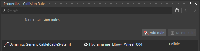
- Create a Collision Rule Container from the Basics section of the Toolbox.
- Create a rule to disable collisions between the Dynamics Generic Cable node of the cable system and the Hydramarine_Elbow_Wheel_004 part.
- Run your mechanism to see the crane in action and see the textured cable that you created.
Adding Joystick Control
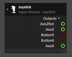
- Go to the Input Devices section of the Toolbox and double-click on the Joystick object to add it to your crane mechanism.
- Move the gamepad sticks and buttons to see that their current values are reflected in the object's property sheet, even if the simulation is not running.
- Go to the Basics section of the Toolbox and double-click on Connection Container to add it to your mechanism.
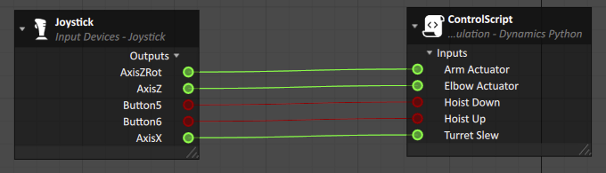
- Drag-and-drop the AxisX, AxisZ, AxizZRot output properties, along with Button5 and Button6 to the Connections Editor.
- Go to the Simulation section of the Toolbox and double-click on Script.
- Set the name to ControlScript.
Create five Input properties and four Output properties as shown in the following screenshot, then click on OK to close the dialog.
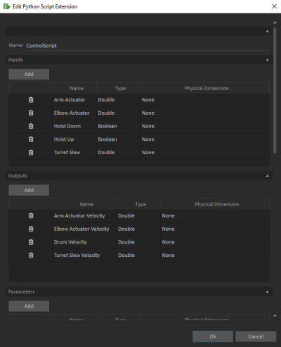
You should be careful to use follow the proper spelling for each property and to select the correct data type as you create script inputs and outputs. Otherwise, you will run into issues when you copy / paste this tutorial's code into your script.
- Drag-and-drop the five input properties of your new script to the Connections Editor and connect them to the existing joystick properties.
Add the following code to the Script section of the Script object. Make sure to click on the Apply button after adding it so that the code is validated and saved in the Script object.
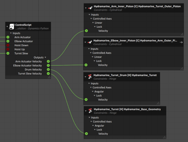
from VxSim import * def pre_step(self): self.outputs.Arm_Actuator_Velocity.value = self.inputs.Arm_Actuator.value * 0.2 self.outputs.Elbow_Actuator_Velocity.value = self.inputs.Elbow_Actuator.value * 0.2 if self.inputs.Hoist_Up.value: self.outputs.Drum_Velocity.value = -0.2 elif self.inputs.Hoist_Down.value: self.outputs.Drum_Velocity.value = 0.2 else: self.outputs.Drum_Velocity.value = 0.0 self.outputs.Turret_Slew_Velocity.value = self.inputs.Turret_Slew.value * 0.2- Drag-and-drop the script's four output properties to the Connections Editor.
- Drag-and-drop the Lock Velocity properties of the four locked constraints that were created earlier in this tutorial.
- Connect the script's outputs to each of the lock velocities.
- Save the crane mechanism.
- Run the simulation and move the assigned gamepad joysticks and buttons to see the crane move in the editor. You should also try to hoist the cable down and see how it interacts with the crane and with the grid of the mechanism editor.
Adding Hooking Logic
Add a Hook Group to your crane hook and assign the Hooking property to an unused toggle button of the Joystick. Please refer to Cables Module 2: Creating Hooks and Loops to learn how to do that.
Adding the Offshore Crane to the Vessel
- Edit your crane's assembly.
- Right-click on the Hydramarine_Base_Geometry part and create a new attachment point.
- Move the point to be at the base of the crane.
- Rename the new attachment point to Vessel AP.
- Select the Hydramarine_Base_Geometry part and set its Control back to Dynamic.
- Save the crane mechanism.
- Edit the vessel mechanism, then edit the vessel assembly.
- Select the Normand_Kraken part and create a new attachment point.
- Rename the new attachment point to "Crane AP".
- Move the attachment point so that it is right at the deck level, where you will want the crane to be positioned.
- Save the vessel assembly.
- Edit the marine scene.
- Go to the Basics section of the Toolbox and double-click on Mechanisms from File object to add your offshore crane to the scene.
- Expand the Vessel mechanism and its assembly to reveal the Crane AP attachment point.
- Expand the Crane mechanism and its crane assembly to reveal the Vessel AP attachment point.
- Press down the Ctrl key and select the Crane AP and Vessel AP attachment points.
- Right-click and select Create Attachment.
- Click on the Snap parameter to automatically align the two attachment points.
- Save the scene and run it to see that you will be able to control the crane that is now attached to the vessel.
Adding a Liftable Object to the Vessel Deck
- Go to the Basics section of the Toolbox and double-click on Mechanisms from File object to add a liftable object to the scene, found under ..\CM Labs\Vortex Studio Content <VERSION>\Demo Scenes\Equipment\SubseaModules\EDP\Dynamics\Design in the file EDP.vxmechanism.
- Place the EDP (Emergency Disconnect Package) mechanism on the deck of the ship.
- Create a Hook Group and a Loop Group, with the Hook being the attachment point at the end of the crane cable, and the loop being the top attachment point of the EDP cable.
- Using a Connection Container, assign controls to the gamepad to activate the hook group in order to lift the EDP mechanism.
- Save and Run the scene.
- Control the crane to make its cable approach the shackle at the top of the EDP. When the hook block is in range, green spheres should appear on the hook block and the EDP hook.
- Press the assigned Hook Button to engage the hooking mechanism.
- Once the green spheres disappear, lift the EDP off the ship desk.