Maritime Tutorial 4 : Subsea Operations
In this training pack, we will go over key concepts and guidelines to get you started with nautical simulations in Vortex® Studio.
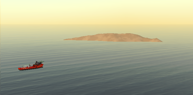
This module focuses on using Vortex Studio to create an ocean floor environment, as well as adding tooling to an ROV.
Prerequisites
You need to have Vortex® Studio and the Vortex Studio Demo Scenes installed to be able to follow all steps in this tutorial.
Adding an Ocean Floor and ROV Manifold
- Open the Marine scene created in Module 1.
- Use the middle mouse in conjunction with the CTRL key to position the camera underwater.
Run the simulation.
You will see that a few silt particles are going to be automatically generated and moving around in the water. You will also see that if you keep moving deeper and deeper, you will never reach an ocean floor. By default, the ocean is bottomless in Vortex Studio. To have an ocean floor, we must load a 3D model or graphic gallery to represent the bottom of the ocean.
- In the Explorer, expand the Ocean Dynamics section to find Ocean Graphics, expand that branch as well to find Silt Particle.
- Increase the particle size to 0.2m to make them more visible.
- Run again to see the results of this modification.
- Go to the Environment section of the Toolbox and double-click on Terrain from File...
- In the dialog that appears, browse to the ...\Vortex Studio Content <version>\Demo Scenes\Environment\Offshore_Environment\Graphic directory and select the file Offshore.vxgraphicgallery.
- Set the Default Material to "Ground" (case-sensitive).
Complete the terrain import by clicking on the OK button.
The seabed graphic gallery will be very hard to see at first since its configuration as part of our sample set is to only display itself if you are very close to its center. In the next few steps, we will modify this viewing distance.
Double-click on the seabed graphic gallery to edit it.
Select the SeaBed node and chante the Maximum Distance in section 0 of Levels of Details to a value of 1000m
Save the seabed graphic gallery and go back to the scene. You should now see the terrain loaded if you're close enough to it. The Levels of Detail parameter determines how close you need to be to the center of the graphic node to see it.
Since the terrain loads at the origin of the scene, most of
- Select the Offshore terrain node in the Explorer and change the Z translation parameter to -600.
- Move the camera further underwater until you find the sea bed.
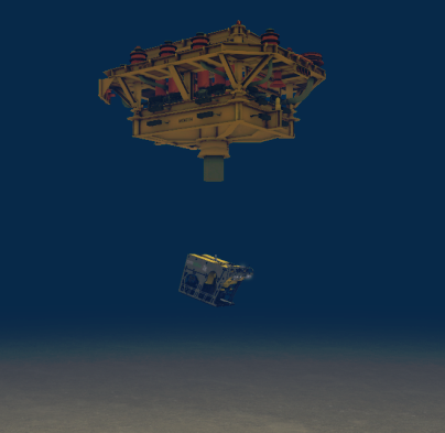
- Using the Toolbox, import the ManifoldStack.vxmechanism file found in the ...\Vortex Studio Content <VERSION>\Demo Scenes\Equipment\SubseaModules\Manifold directory.
- Change the mechanism's Z translation to -586.0m. This will place the mechanism a few meters above the ocean floor.
- Right-click on the manifold and select the Center in Active View option to center the camera on this object.
- Right-click on the eye icon next to the ManifoldStack mechanism and select Geometry to see the mechanism's simplified collision geometries.
- Hide the mechanism's collision geometries.
- Save the scene.
Adding an ROV Mechanism
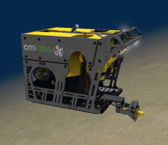
- Using the Toolbox, import the WorkClassROV.vxmechanism file found in the ...\Vortex Studio Content <VERSION>\Demo Scenes\Equipment\ROV\WorkClassROV directory.
- Change the ROV's Z translation parameter to lower it to the sea bed.
- Move the ROV to be positioned near the manifold.
- Run the simulation to see that the ROV's buoyancy is not stable, leaning in a certain direction. Its buoyancy has currently been defined to be stable when it has tooling attached on the front of the unit.
- Modify the ROV's buoyancy to make it stable underwater (Center of Buoyancy under Generic_HD_ROV part).
- Select the Ocean Graphics component in the Explorer and reduce the Underwater Fog Distance to 5m.
- Run the simulation and press the C key to change the viewpoint to the ROV's camera. See how little visibility you have.
- Use the controller to move closer or further away from the manifold. See how the ROV collides with the manifold based on each mechanism's collision geometries.
- Save the scene.
We will now create a simple torque tool, primarily to be used for accessibility studies, and attach it to the ROV.
Creating a Torque Tool Mechanism
- Go to the top Vortex Studio menu and create a new mechanism.
- Use the Toolbox to import a graphic gallery, then select the FLOT_With_TT_2.vxgraphicgallery in the ...\Vortex Studio Content <VERSION>\Demo Scenes\Equipment\ROV_Tools\FLOT_accessibility\Graphics directory.
- Rotate the graphic gallery 90 degrees before starting to create the mechanism.
- Create an empty assembly in your mechanism and rename it to "TorqueTool".
- Create parts from the FLOT_And_TorqueTool2 top-level node in the gallery and the TorqueTool__Plate_DOF node.
- Edit the FLOT_And_TorqueTool2 part and:
- Set mass to 500 kg.
- Auto compute the inertia tensor and COM.
- Create collision geometries to properly be able to simulate accessibility of the torque tool. Useful shapes in this case are the capsule and boxes.
- Set the material on all collision geometries to Chassis
- In the assembly, set the FLOT_And_TorqueTool2 part to be Static temporarily for testing.
- Create a Hinge constraint between the FLOT_And_TorqueTool2 parts, and:
- Select TorqueTool__Plate_DOF first.
- Set the Primary Axis of Part 1 to X+
- Set the Secondary Axis of Part 1 to Z+
- Go to the Offset (relative) section of Part 2 and Apply.
- Set Control to Locked under Controlled Axes
- Set the Lock Velocity to 90 degrees/s
- Set Limits to 0 degrees as the Lower Limit and 3600 degrees as the Upper Limit.
Save the torque tool assembly and mechanism.
We can see that the Torque Tool has many more mechanical components to be able to tilt the tool and adjust other positional elements of the tool. We will not be modeling all of these complexities in this tutorial, but they could all be represented in Vortex Studio.
- Go back to the mechanism level and run the simulation. The front plate of the torque tool will move in a circular motion.
Attaching the Torque Tool
- Back at the assembly level, set the Control of the FLOT_And_TorqueTool2 part back to Dynamic.
- Right-click on the FLOT_And_TorqueTool2 part and create an Attachment Point.
- Rename the attachment point to "ROV AP" and leave it at the origin of the assembly (0, 0, 0).
- Go back to your marine scene and center the view on the ROV.
- Use the Toolbox to insert the new torque tool mechanism in your scene.
- Expand the ROV mechanism, its assembly, its Attachment Points folder, and its Tooling folder to find the "FLOT Connection" attachment point.
- Expand your Torque Tool's assembly to find the "ROV AP" attachment point.
- Select both and right-click to create an Attachment Point between the two attachment points.
- Save the scene, and all other open files.
Adding Torque Tool Control Logic
- Go back to editing the torque tool mechanism.
- Add a new Dynamincs Script to the mechanism for user control and to calculate how many turns the torque tool has travelled.
- Rename the script to "ControlAndHUDDisplay".
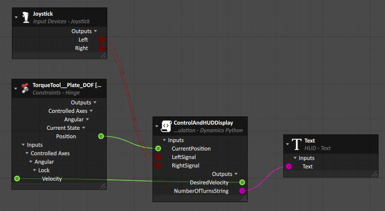
Configure the inputs and outputs to match the image below:
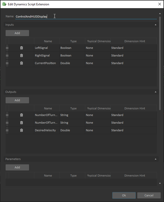
Data types being used in this script: Boolean: Data type which may only have one or two values (ie. True or False, 1 or 0). Double: A double-precision floating point data type. Mathematical operations can be used on this data type. (ex. 1227.39, 5.19e^-10). String: Sequences of character data. Mathematical operations cannot be used on this data type. (ex. "Hello world!", "4").
Set the code of the Script file as follows:
def pre_step(extension):
    if extension.inputs.LeftSignal.value and extension.inputs.CurrentPosition.value >= 0 :
        extension.outputs.DesiredVelocity.value = -0.5
    elif extension.inputs.RightSignal.value:
        extension.outputs.DesiredVelocity.value = 0.5

    extension.NbTurns = int( ( extension.inputs.CurrentPosition.value * 57.2958 ) / 360 )
    extension.outputs.NumberOfTurnsOnly.value = str( extension.NbTurns ).zfill(4)

    extension.outputs.NumberOfTurnsString.value = "Number of turns = " + str( extension.NbTurns )
- Go to the HUD category of the Toolbox and add a Text object to the mechanism.
- Change the Anchor Position to be 0.7, -0.95 and 0.0.
- Create a Connection Container using the Toolbox.
- Select the ControlAndHUDDisplay script and drag-and-drop the object's CurrentPosition input, NumberOfTurnsString and NumberOfTurnsOnly output properties to the Connections Editor.
- Select the Hinge constraint and drag-and-drop the Position output from the constraint's Current State, as well as the Lock Velocity input property to the Connections Editor.
- Add a Joystick object to the mechanism from the Toolbox.
- Drag-and-drop the joystick's Left and Right output properties to the Connections Editor.
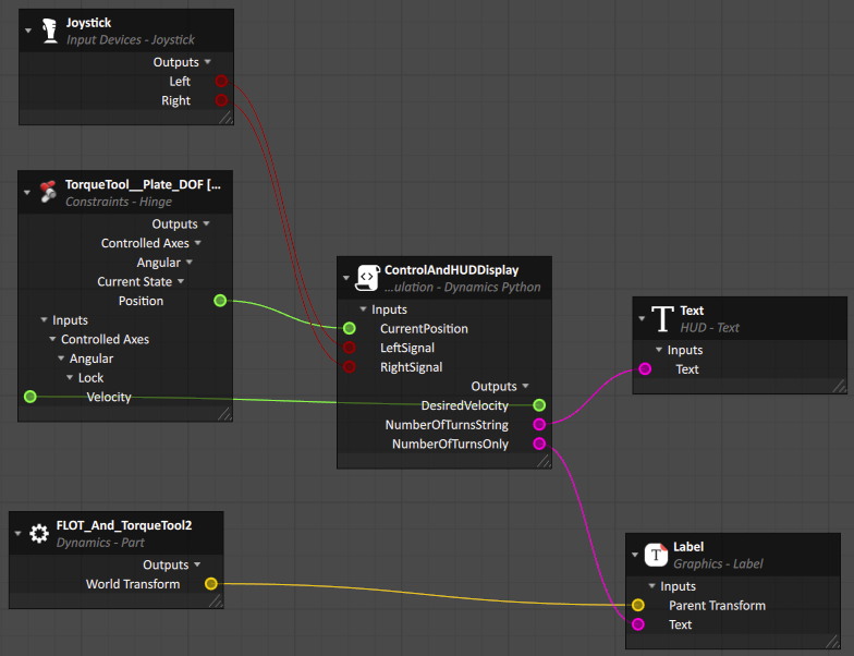
- Draw connections as shown in the diagram below.
- Go to the Graphics category of the Toolbox and double-click on Label.
- Set the Text Size to 48.
- Set the Font Height property to 0.05.
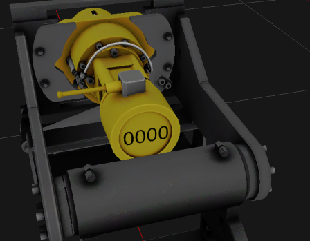
- Set the Text property of the Label to 0000 to have representative content for placement.
- Use the movement and rotation controls to position the text on the front part of torque tool.
- Drag-and-drop the World Transform output property of the FLOT_And_TorqueTool2 part to the Connections Editor.
- Drag-and-drop the Parent Transform property of the Label object to the Connections Editor.
- Drag-and-drop the Text property of the Label object to the Connections Editor.
- Draw additional connections to complete the bottom part of this diagram. Once these new connections are made, the label will only display when the simulation is running.
- Save all open files.
- Run the mechanism to see the newly created element display in the bottom-right corner. Use your gamepad's left and right directional arrow to turn the torque tool and see the number change after each full turn.