Publishing TF2 over ROS2 from a mechanism
In this tutorial, users will learn how to create a mechanism that will publish a TF2 data structure over a ROS2 simulation.
Prerequisites
You must have Vortex® Studio and the Vortex® Studio's Samples installed to be able to complete this tutorial.
In addition, a compatible version of ROS2 needs to be installed on the computer. Make sure that the bin folder of the ROS2 installation is in the PATH of the context from which Vortex® Studio's Editor will be launched.
Before starting this tutorial, we recommend you have the Getting Started Tutorials covered first. Users needs also to have some knowledge in ROS2. Otherwise, we recommend to follow the ROS2 tutorials that can be easily found on the web. At least, the beginner level should have been covered before going through this tutorial.
In this tutorial, we suppose that the user wants to publish over ROS2 a set of poses that are simulated in Vortex®. For this end, we will use a simple 4 wheels vehicle that is part of the Vortex® Studio's Samples. At the end, the chassis and the wheels of the vehicle will be set in a TF2 tree. The chassis will be the parent pose of the wheels.
ROS2 Module
Take note that any Vortex® Studio's Application that will use ROS2 C++ extensions requires that the ROS2Module is part of the setup file. See ROS2Module . To add the ROS2 Module to the current setup file do the following.
- Verify that the ROS2Module is part of the setup file.
- From the main page of the Vortex® Studio's Editor, choose "Options".
- Choose the tab "Setup".
- Under "Application Setup" open the current vxc file.
- In the "Explorer" panel search for ROS2 Module. If it exist, simply close the setup document editor. Otherwise, find the ROS2 Module in the Toolbox, double clic on it and save the vxc file. Let the Editor restarting the application.
Load a mechanism
- Started the Vortex® Studio Editor.
- Do file Open and navigate to the folder "Samples\assets\Vehicles\Car - Hatchback". Open the mechanism file called "Car - Hatchback.vxmechanism".
- Right click on the 3DView, select the grid option and choose "Use Grid".
Create a Transform Broadcaster extension
- In the Toolbox, search for the Transform Broadcaster in the ROS2 category. Add one instance by double clicking on it.
- The Transform Broadcaster use a rclcpp::node. Choose a name for it, say CarTFBroadcaster.
- Optionally, choose a namespace for the node.
Create Transform Stamped extensions
In this use case the user wants to broadcast the pose of the chassis of the vehicle and its 4 wheels. He also wants to see the pose of the wheels in the reference frame of the chassis.
- From the Toolbox, find the Transform Stamped extension.
- Create 5 instances of the extension.
- Set the Broadcaster to each of them.
- Have the Transform Stamped instance selected.
- Drag the instance of the Transform Broadcaster extension from the Explorer panel and drop it on the field called "Broadcaster". (tip: multi-select the 5 Transform Stamped extensions)
- Set chassis part of the vehicle to broadcast its pose.
- Navigate the Explorer view until the chassis part.
- Drag the part onto one of the "IMobile" field of a Transform Stamped.
- Enter a name for this Transform Stamped, into the Frame ID field. Say "chassis"
- Do the previous steps for each of the wheels. As per TF2 request, choose a different name for each of the "Frame ID".
- Take a look at the Explorer panel and notice that each Transform Stamped have taken the name of the Frame ID.
- As a final step, from the Explorer panel multi-select the wheels (by holding Ctrl and clicking on each wheels) and drag them over the Transform Stamped extension called "chassis" also in the Explorer. This step make all the wheel to be child of the chassis.
It should look like in the following screenshot after the move is performed.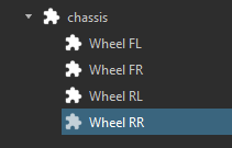
Testing the setup
At this point, the mechanism file can be saved. It is ready to be used in a co-simulation with ROS2. But as final quick step, it's would be a good idea to verify the integrity of the setup of the extensions.
To do so, start the simulation and look for any error messages that may appear in the Explorer panel. We hope that such messages, if any, will be self explanatory enough for the user to fix them. In addition to the error messages in the Explorer panel, the log file of the Editor may contains other hints to help fixing the issues. Please, revisit the documentations pages about ROS2 integration Documentation
Running the simulation
When the simulation will be started, each rclcpp::node that is encapsulated in the ROS2 extensions will be created, thus adding the Vortex simulation to any currently running ROS2 simulation on the computer or the network.
When the simulation is stopped, all rclcpp::node are destroyed which removed the Vortex simulation from the ROS2 ecosystem.
Take note: In this example the Transform Stamped referring to the chassis doesn't have a parent, as oppose to each wheel. This would lead the frame_id of the header of the geometry_msgs::msg::TransformStamped to be not set leading to an uncompleted TF2 structure. To avoid this, in Vortex, any orphan Transform Stamped takes the value of "Root Frame ID". This is found on the ROS2Module extension. The default value is 'map'.
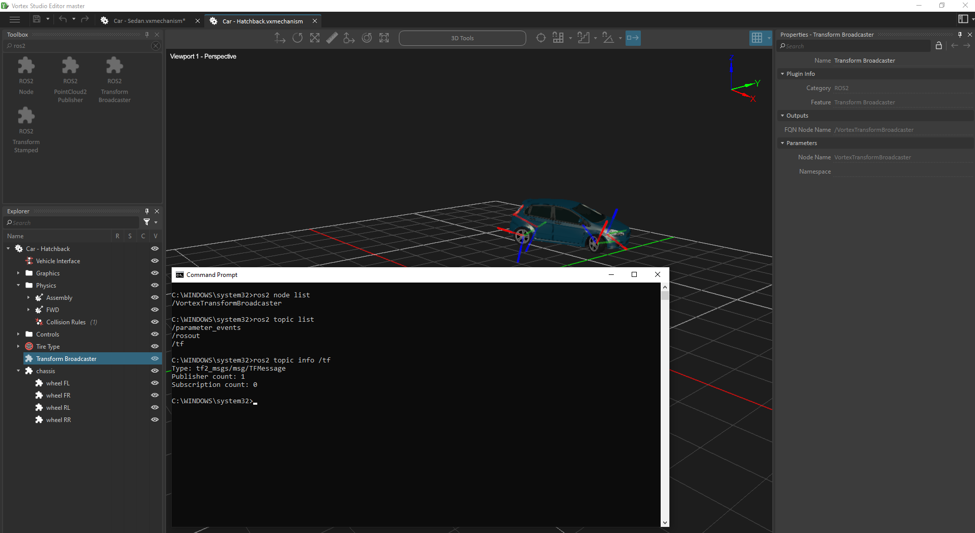
To verify that this is happening, the user can run any ROS2 tool from a command window like for example ros2 node list or ros2 topic list.
An other useful tool from ROS2 is rviz2 which can be of great help specially in dealing with TF and other functionality that requires a 3D view.
Conclusion
User has learned how to create a TF2 hierarchy out of Vortex® mechanism.
We recommend to save the mechanism that has been authored during this tutorial. It will be re-used in the next tutorial. Please choose the following name: 'Car - Hatchback - WithTF.vxmechanism'
Please, follow the next tutorial where users will learn how to manage to use multiple instances of a mechanism in a scene that contains TF2 : Publishing TF2 over ROS2 from a Scene