Making a Co-Simulation Between Vortex and Simulink
This feature is currently in Beta. To enable it, define the environment variable ENABLE_SIMULINK_FEATURE before launching your Vortex application.
Introduction
The Simulink Plugin comes pre-installed with Vortex. If you have Simulink installed on your system, it allows you to transfer information between Vortex and Simulink while simulations are running, allowing co-simulation between the two pieces of software. This guide demonstrates how to set up the communication link between Vortex and Simulink, and how to run a simulation with the information exchange.
Pre-requisites
- To follow this guide you need a valid licensed installation of Matlab and Simulink version R2021b.
Configuration
Configuring Vortex
To configure Vortex, the Simulink module must be added to the Vortex application that Simulink will communicate with. In this example we will use the Vortex Studio Editor but it can be done for any Vortex application.
- Launch the Vortex Studio Editor.
- Open the setup document (.vxc) of the application which will communicate with Simulink.
- For the Editor, there is a quick shortcut. Click Options. Navigate to the Setup pane, and, under Application Setup, click the green button indicated below.
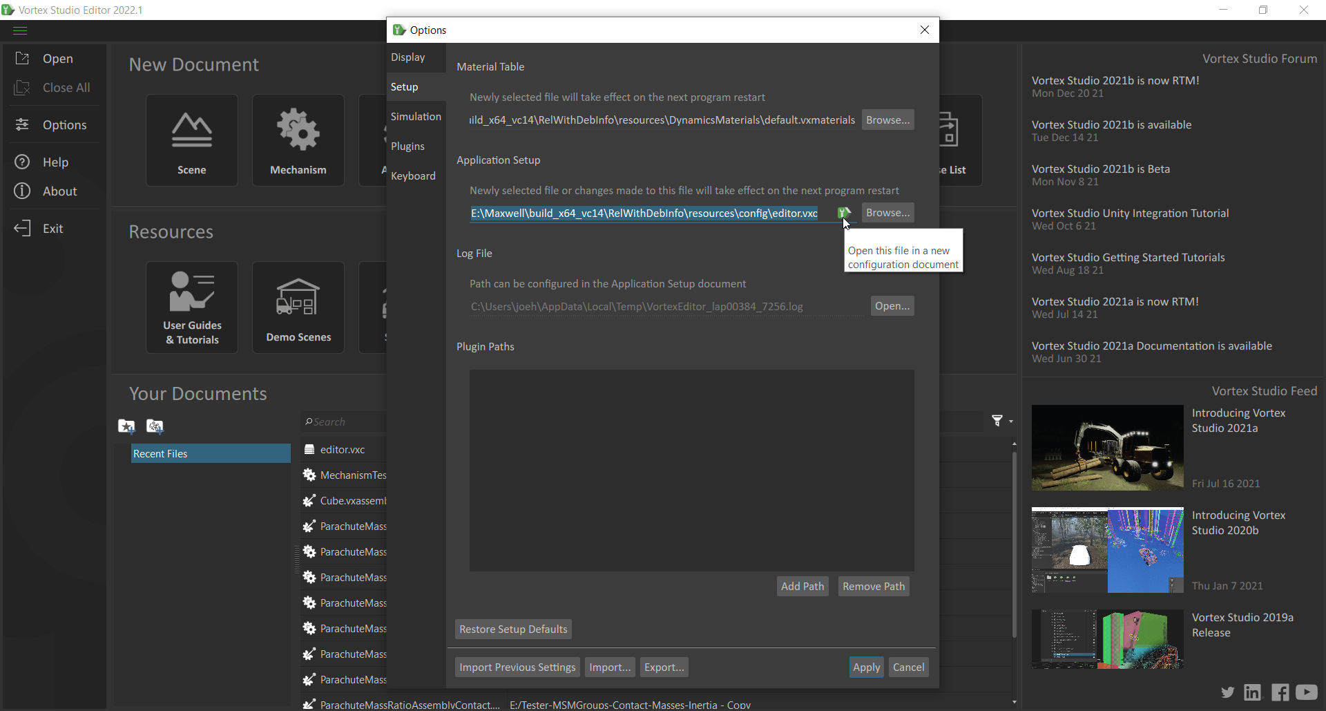
- For the Editor, there is a quick shortcut. Click Options. Navigate to the Setup pane, and, under Application Setup, click the green button indicated below.
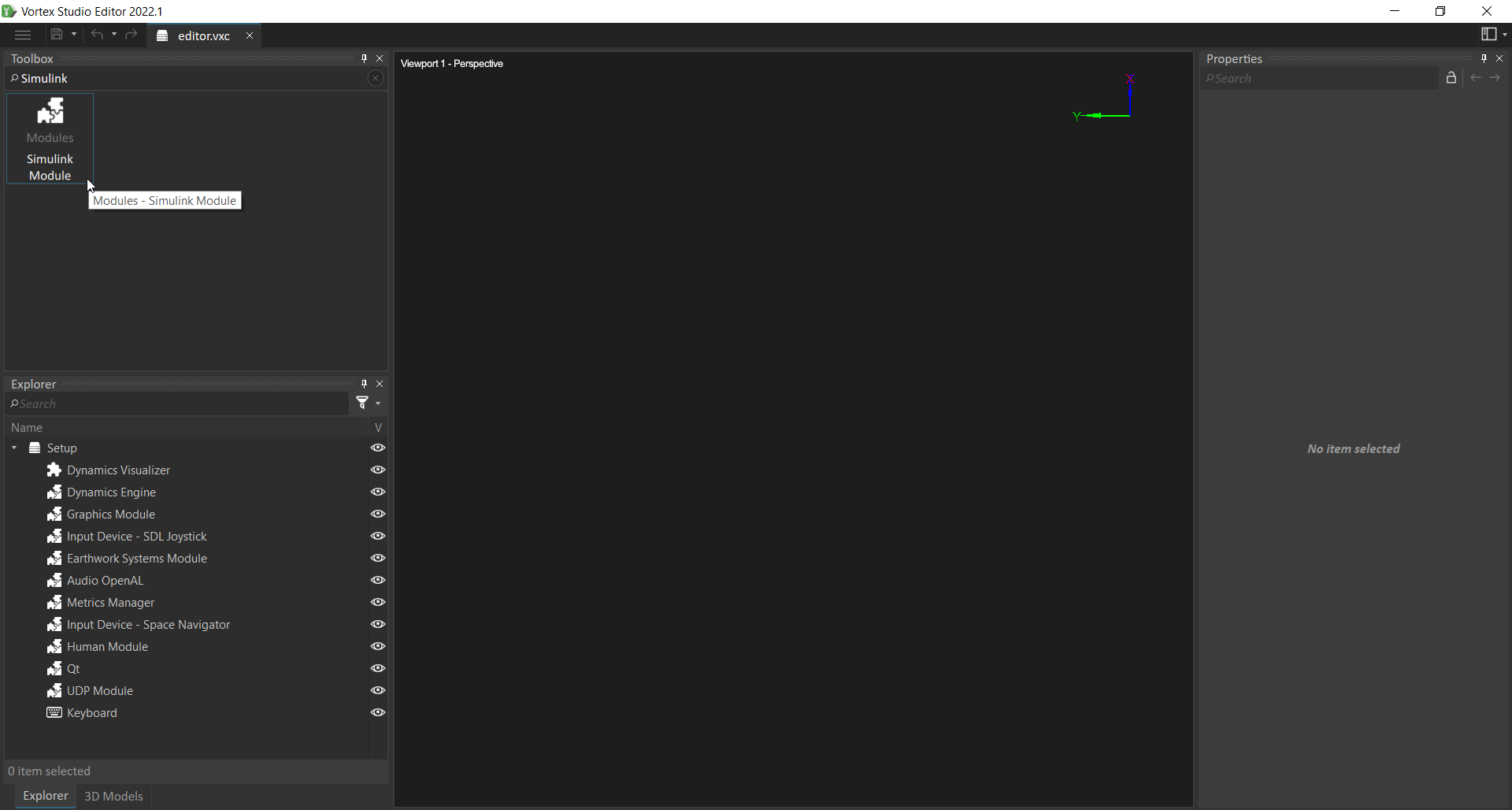
- Once the setup file is open, go to the Toolbox, and search for Simulink. The Simulink Module icon should appear in the toolbox.
- Double-click on the module to add it to the setup document.
Upon being added to the configuration, the properties of the module will appear in the Properties pane. There are three options here:
Option Purpose Configuration Address Allows Simulink and Vortex to communicate over a network If Simulink and Vortex are running on the same machine, the default settings should be fine. If the software is running over a network, enter the IP Address through which the communication should take place. Port Allows Simulink and Vortex to communicate over a network If Simulink and Vortex are running on the same machine, the default settings should be fine. If the software is running over a network, enter the Port through which the communication should take place. 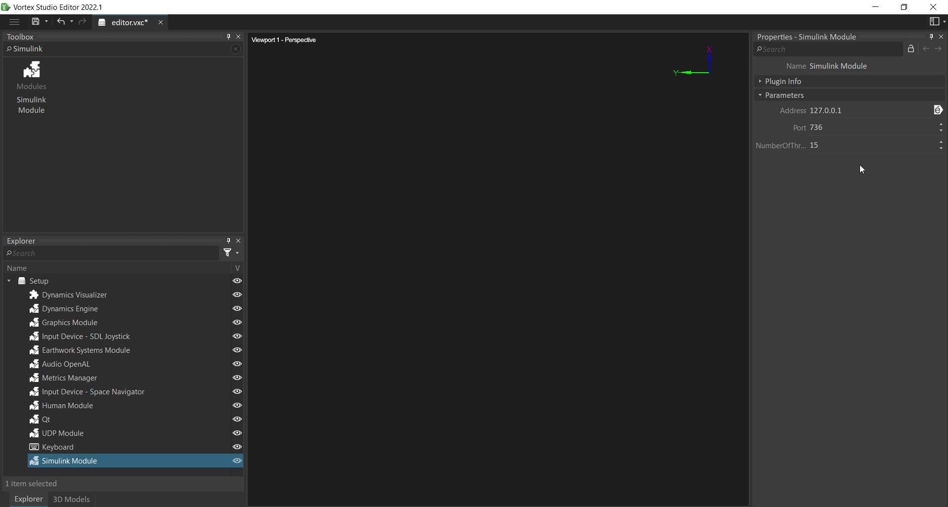
Now, save the setup document by clicking the save button.
Vortex is now configured to send and receive information from Simulink.
Configuring Matlab/Simulink
To configure Matlab/Simulink, the file where the Vortex S-function blocks are stored must be added to the Matlab path in order to make them available for use in the Simulink block library.
- First open Matlab.
- Inside Matlab, navigate to the root folder of your Vortex install. Then, further navigate to the bin/matlab folder.
- The contents of this folder should include 'VortexBlockset.mexw64' as seen below.
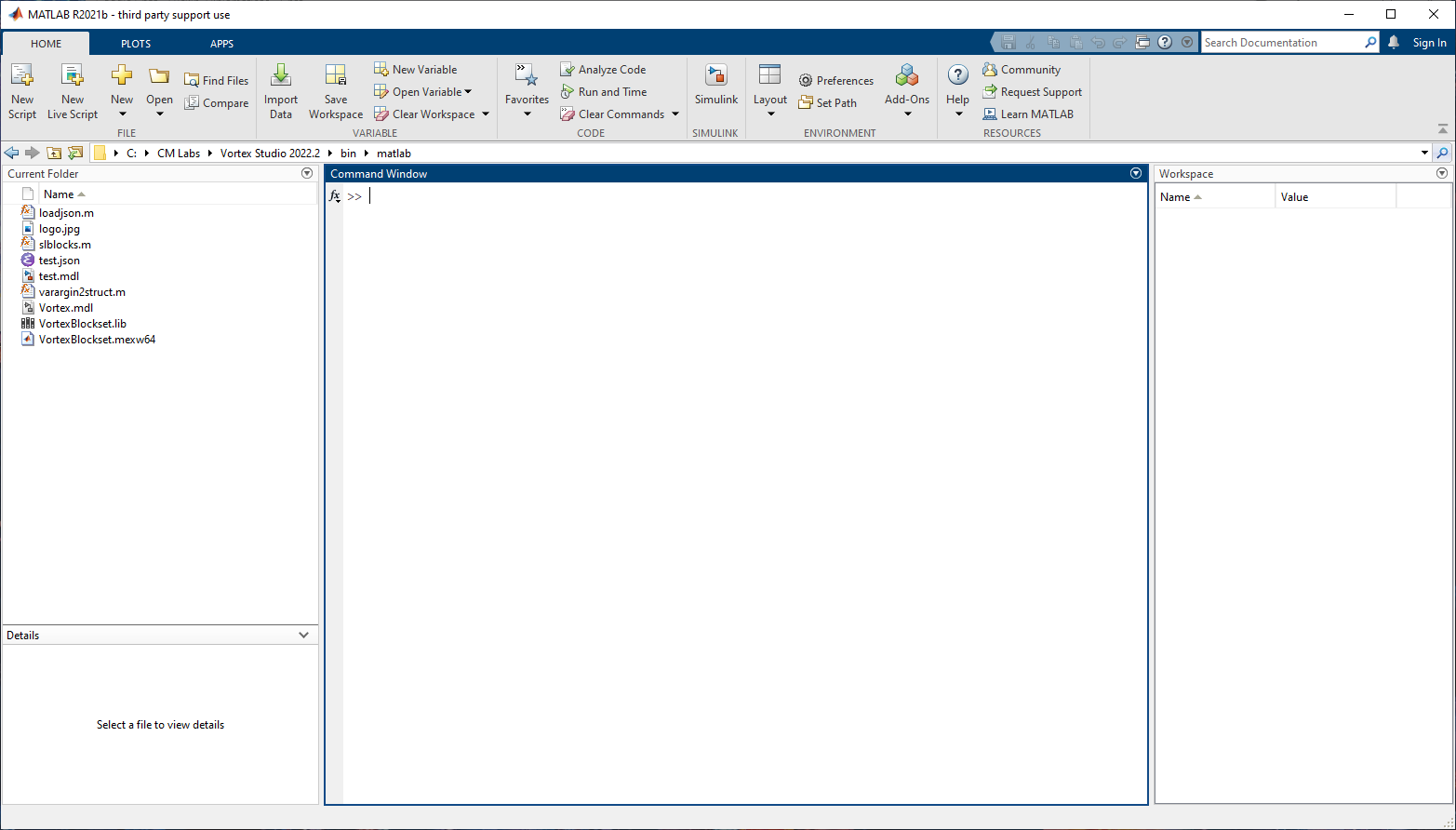
- The contents of this folder should include 'VortexBlockset.mexw64' as seen below.
Once in this folder, type the following command. This adds the current directory to the Matlab path.
addpath(pwd)
- Using the command
pathin the Matlab command line will allow you to check that the folder has indeed been added to the Matlab search path.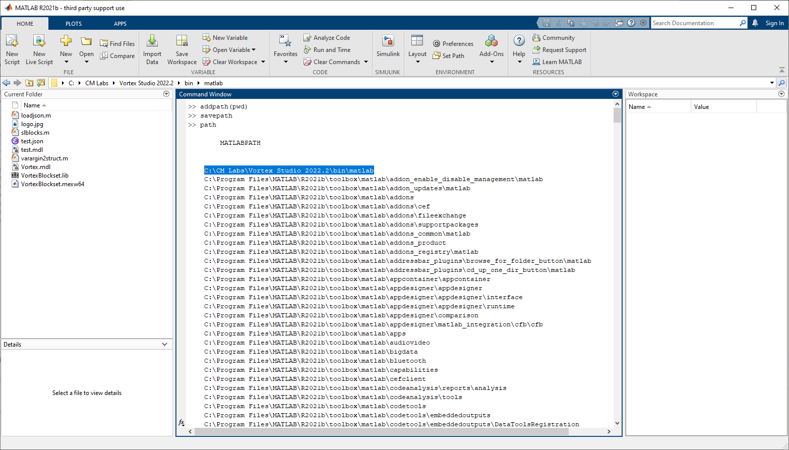
If you wish to permanently add this folder to the Matlab search path (and not just for this session), you can run the command:
savepath
- The configuration of Matlab is now complete. It will now be able to find and use the Vortex S-function block.
Creating the Simulation
The Vortex Simulink Extension
In this section, we will add the Simulink block to a mechanism, and use it to transmit the world transform of a part to Simulink. To provide a demonstration, we will use a Mechanism that contains an Assembly which consists of a single part with a cubic collision geometry.
- Open Vortex Studio Editor.
- Create a new Assembly.
- In the Toolbox, double-click on Part to add a new part to the assembly.
- In the Explorer, right-click on the part and select Create Primitive Geometry. Select a Box.
- Save the assembly.
- Create a new Mechanism.
- In the Toolbox, double-click on Assemblies From Files
- Select the assembly that was just created and click OK.
The content in the Editor should now look like this:
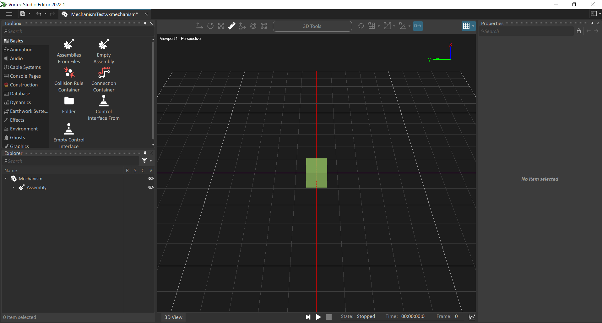
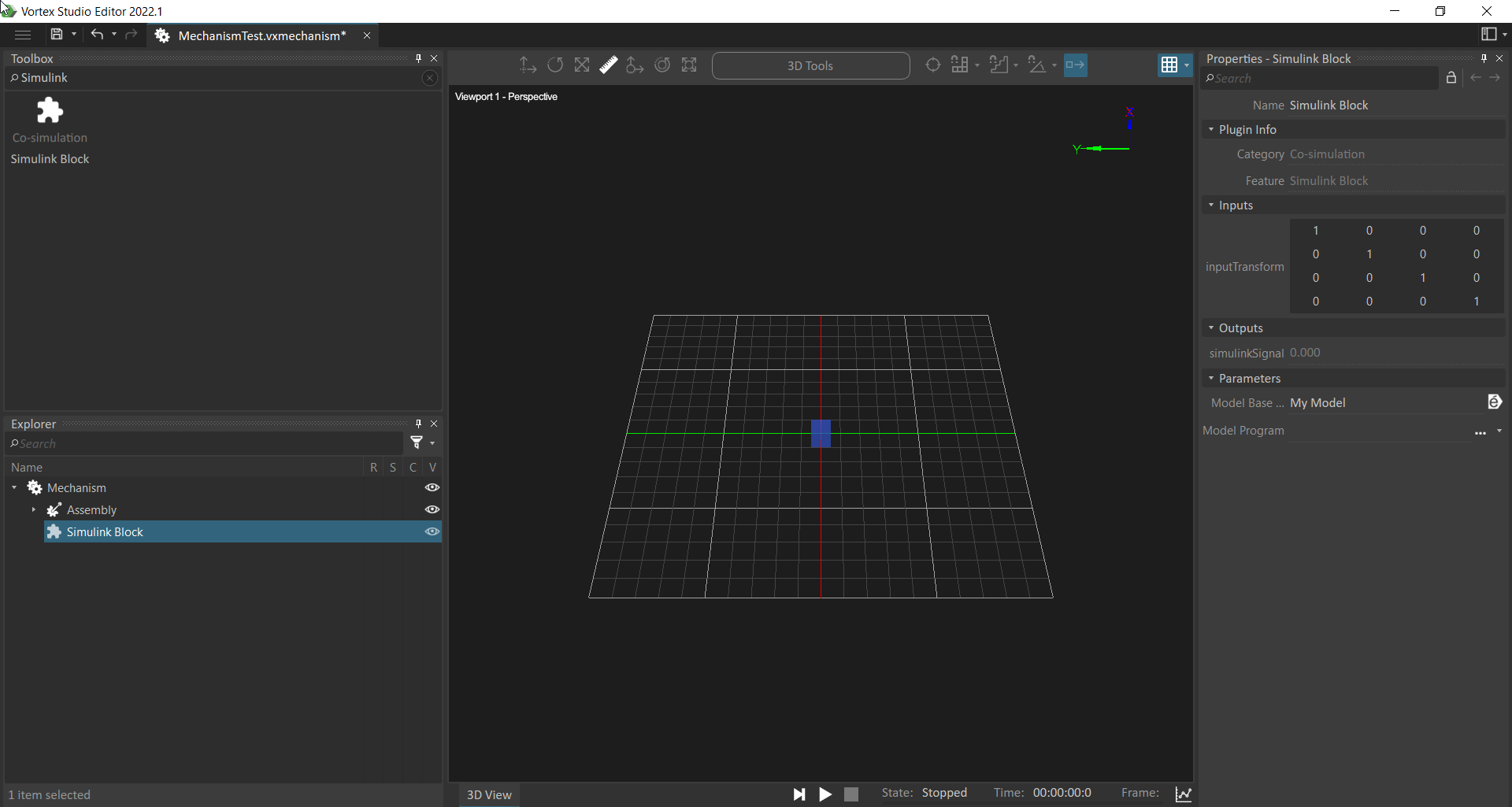
- Search for the Simulink block in the toolbox, and double click to add it to the Mechanism.
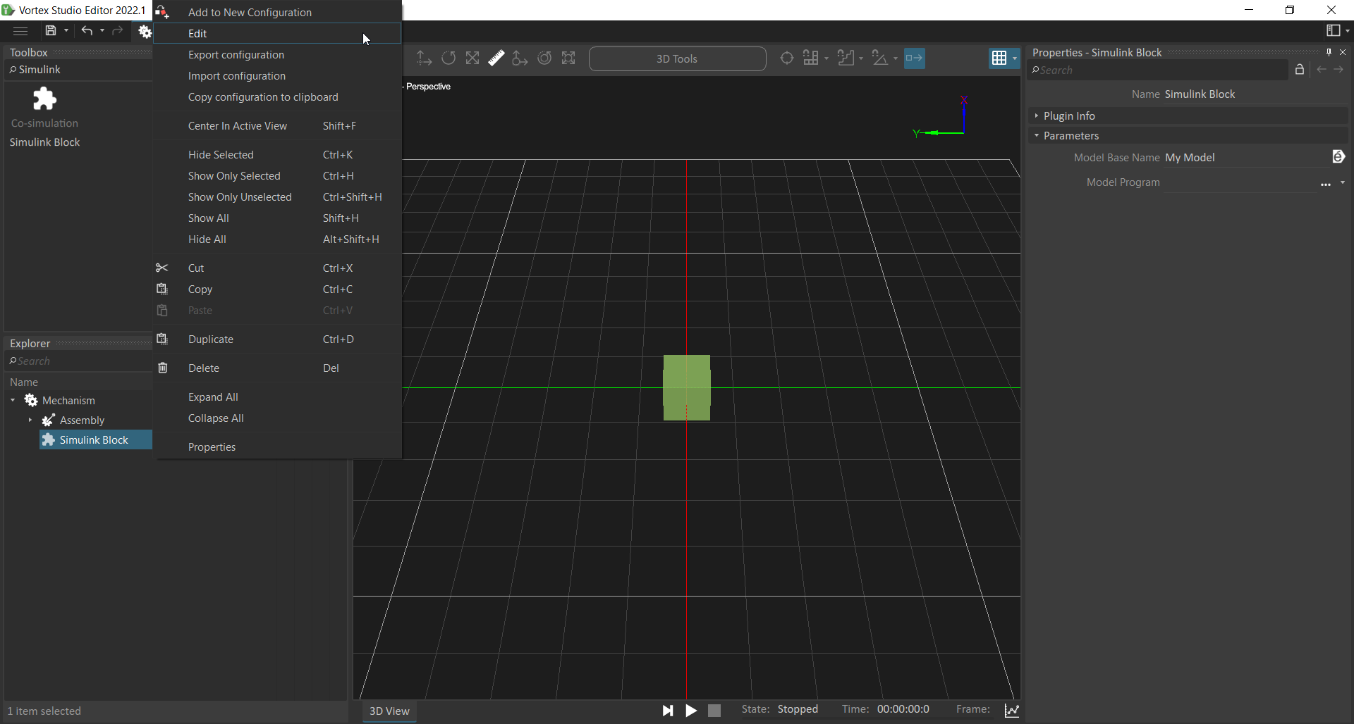
Upon being added, the Simulink extension contains no variables, but it does have two parameters, 'Model Base Name' and 'Model Program'. You can change 'Model Base Name' to whatever signifier you think is appropriate for your task. - In the Explorer, right-click on the Simulink Block extension and select Edit. This will allow you to add variables to the Simulink extension that will be transmitted or received to/from Simulink.
- This brings up the edit field wizard. For this demonstration, we will add a single input, call it inputTransform, and set the type to Transform, we will also add a single output, call it simulinkSignal, and set the type to Double.
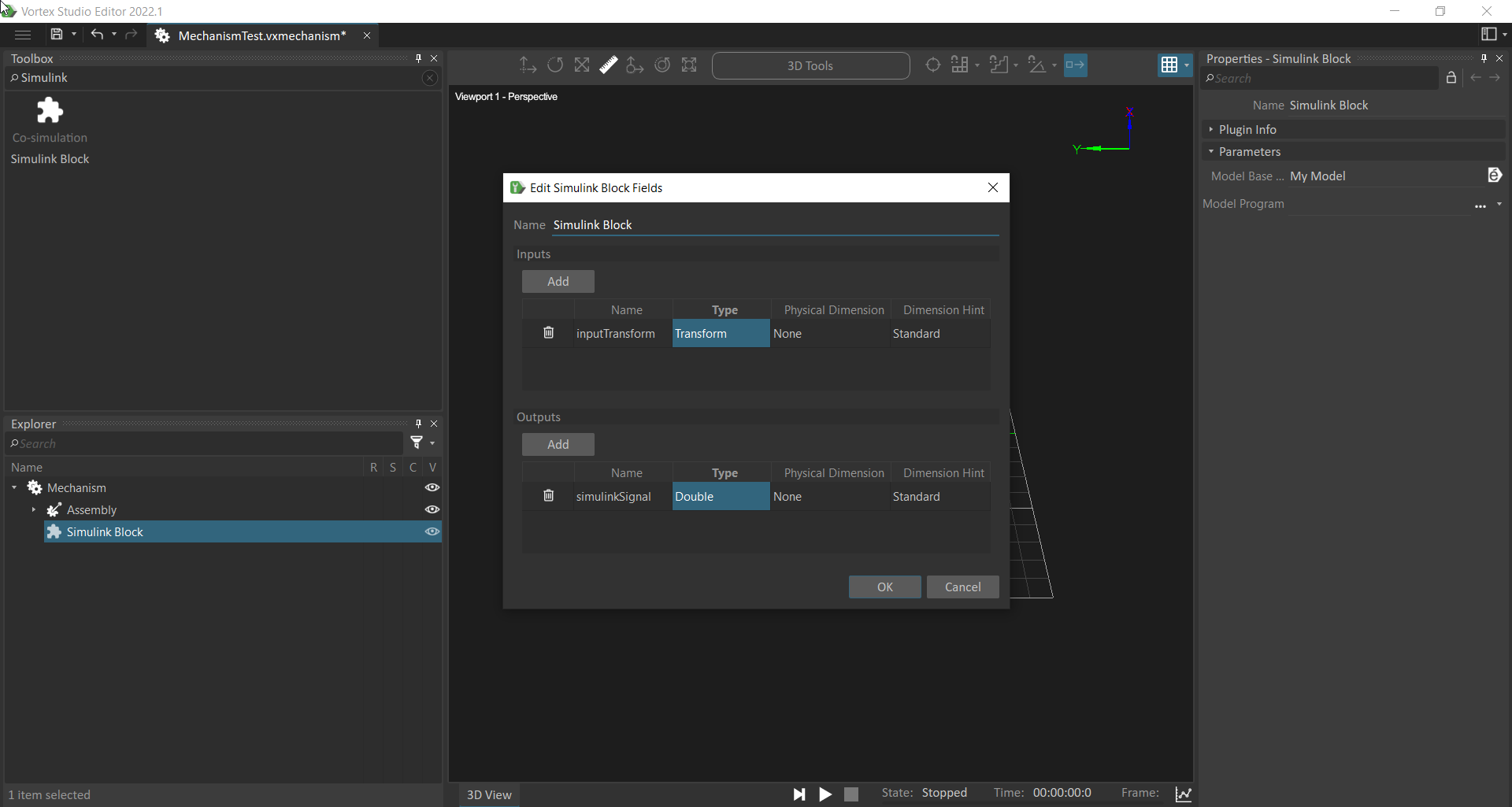
Clicking OK will add the variables to the Simulink extension.
Input variables in the Simulink extension will be those variables which are being sent to Simulink, i.e. they are inputs into Simulink. Output variables are those which will be received from Simulink, i.e. they are Simulink ouputs.
- In the Toolbox, search for Connection Container and double click to add it to the mechanism.
- In the Explorer, click the drop down arrow next to the Assembly extension.
- Select the Part.
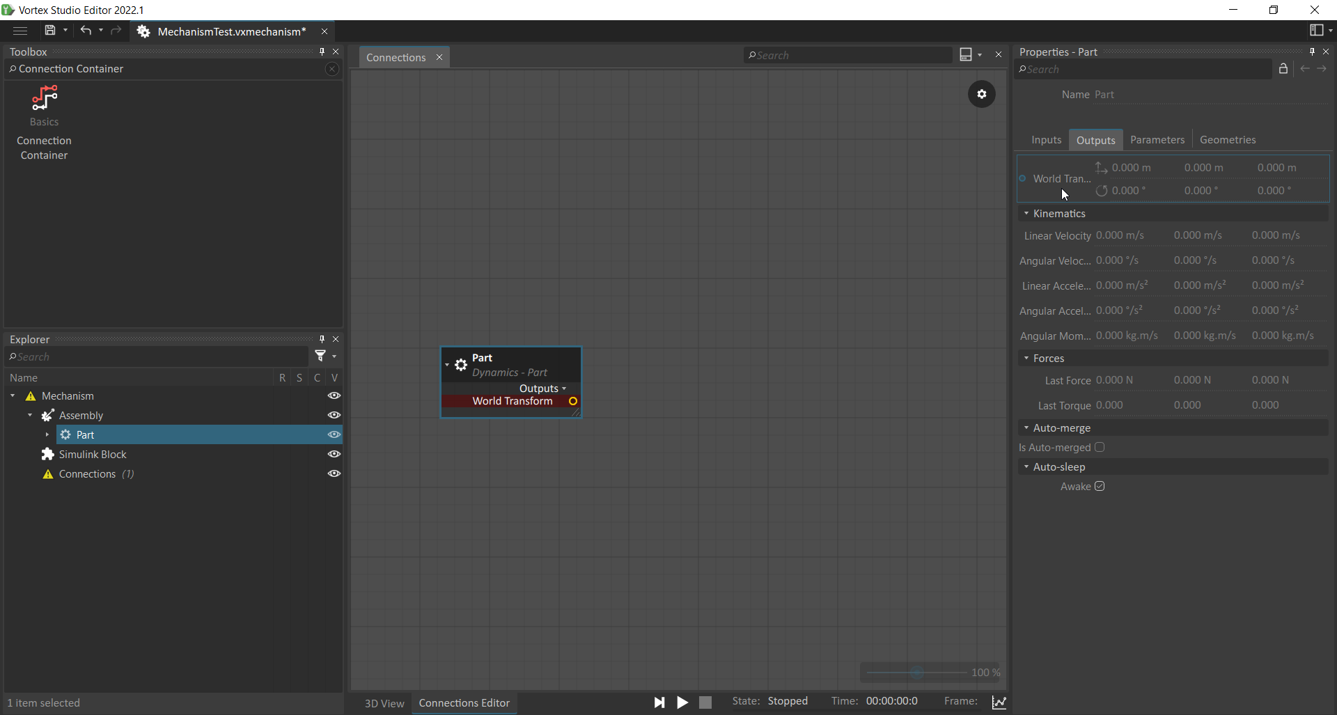
- In the Properties panel to the right, navigate to the Outputs pane and click and drag the World Transform output variable into the Connections editor view.
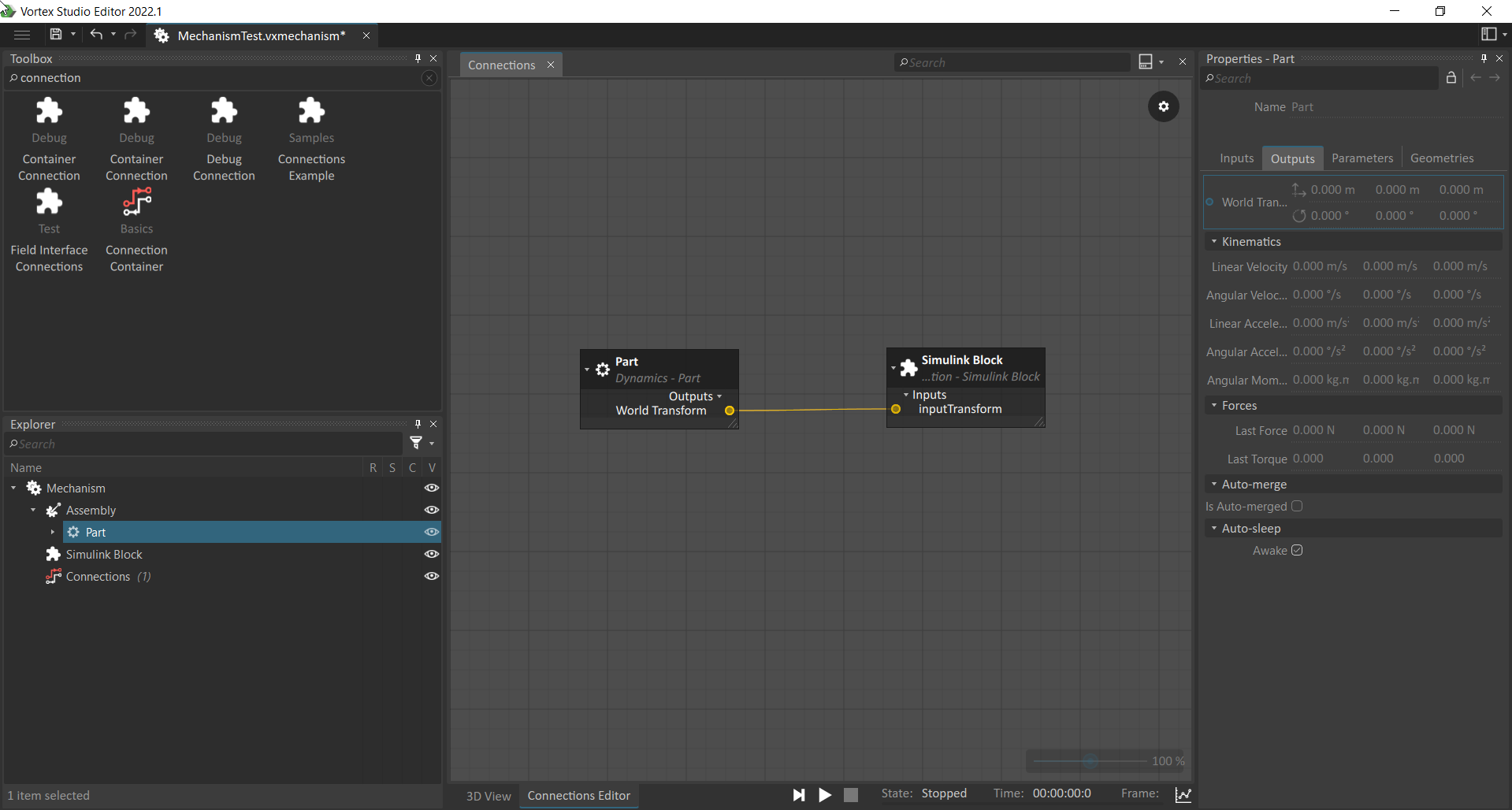
- In the Explorer, select the Simulink extension and drag and drop the 'inputTransform' variable into the connections editor.
- Connect the World Transform output to the inputTransform input by drag and dropping between the two circles.
- Now that we have configured the Simulink extension and determined exactly what variables we will need, we need to create the file which will communicate this information to Simulink.
To do this, right-click on the Simulink Block extension in the Explorer, and select the Export configuration option.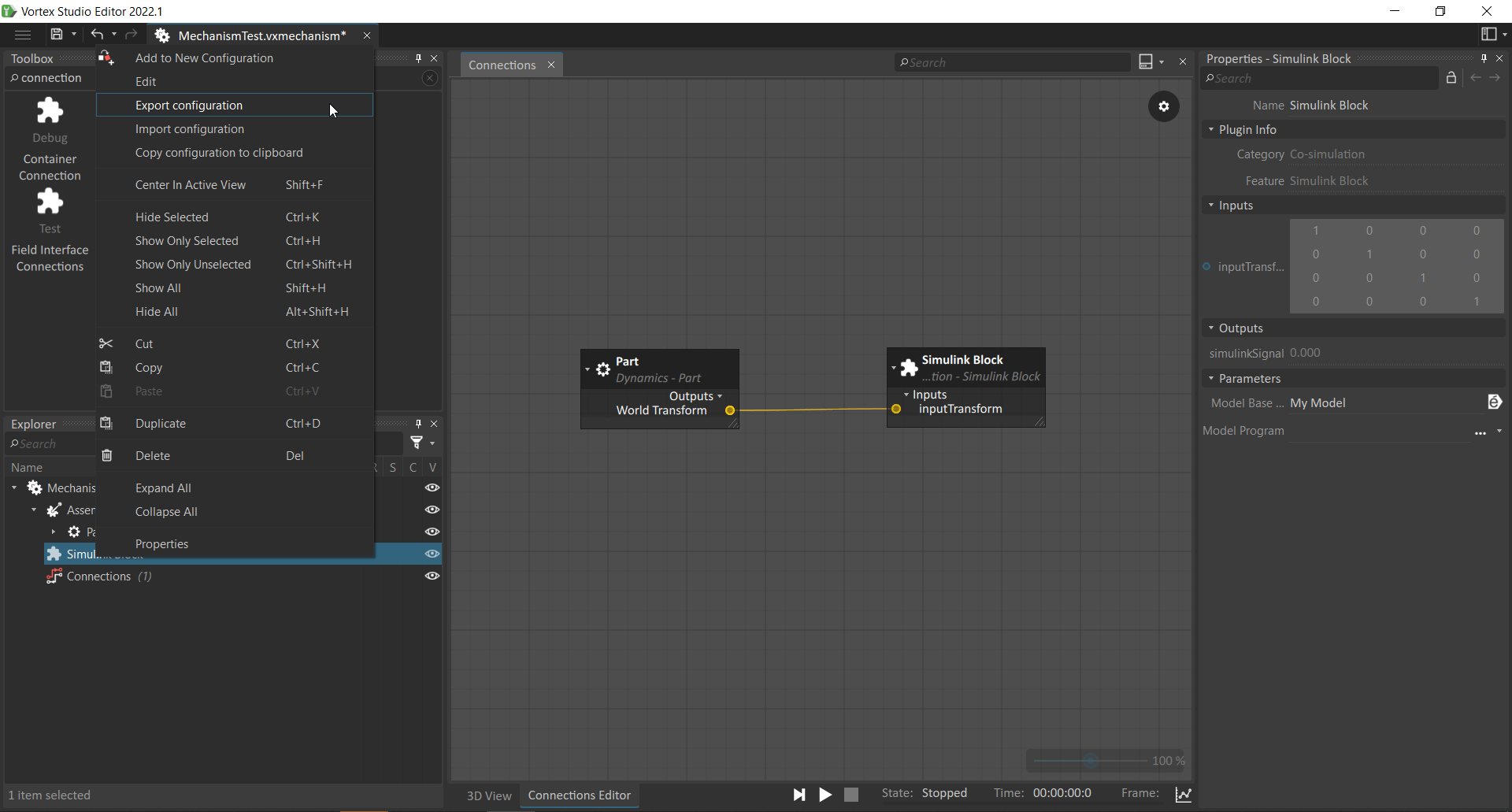
- Save the file with a name and a location of your choosing. It will be needed later to connect Simulink to Vortex.
This is completes adding and configuring the Simulink extension in Vortex.
The Vortex S-function Block
Now we will add the Vortex S-function block in Matlab, and connect it to the previously created Mechanism in Vortex.
- In Matlab, after you have added the correct folder to the Matlab search path as described in the configuration steps in the previous section, open Simulink. Create a new blank model in Simulink
- Click the Library Browser button.
- If Matlab has been configured correctly, you should see an entry for Vortex in the left hand pane. Clicking this displays the Vortex Simulink block on the right hand side. |
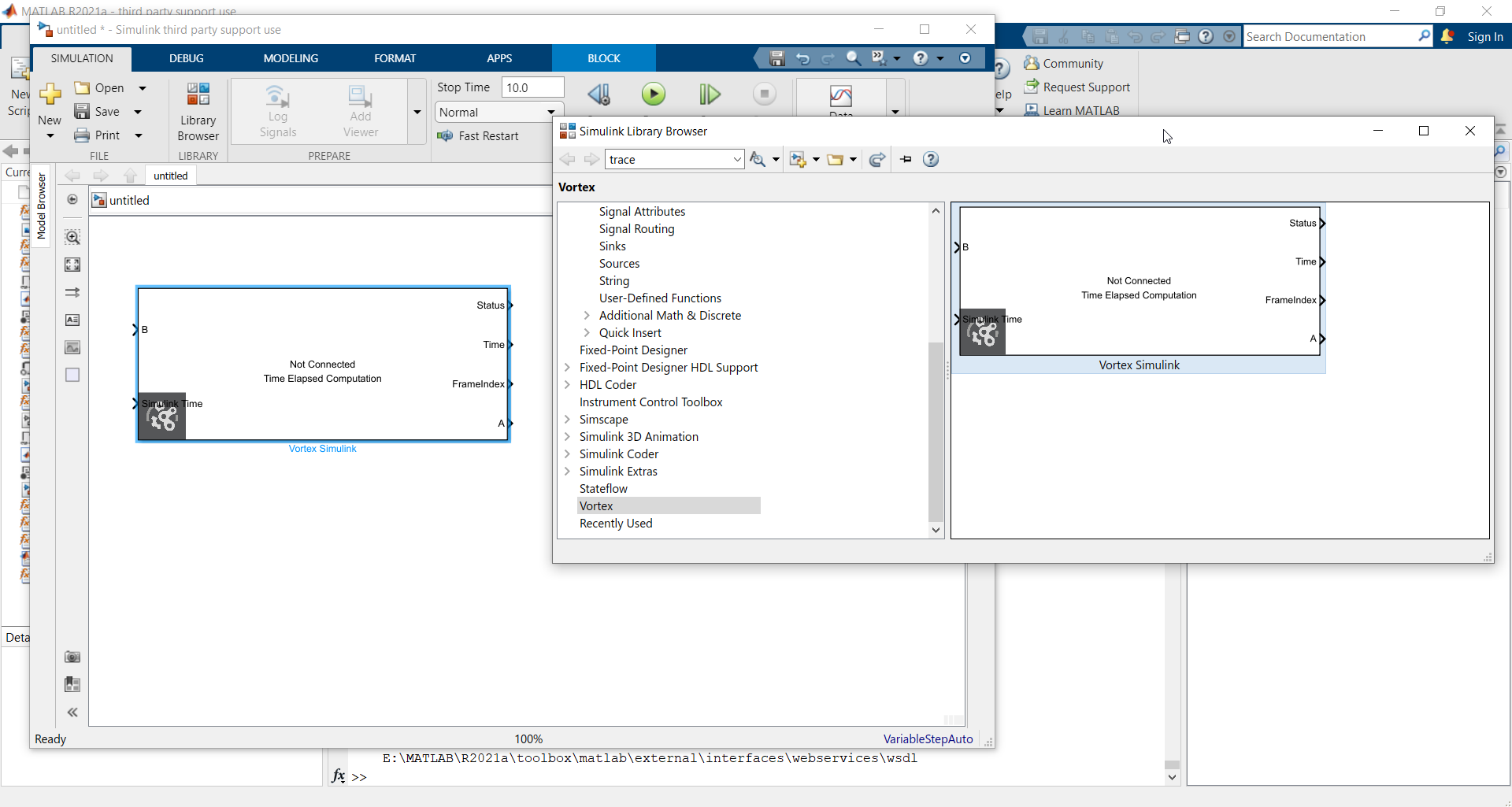
- Click and drag the block into the blank model.
- Double-click on the block to bring up the configuration properties.
- Set the IP and Port fields to the same values as those in the properties of the Vortex Simulink Module, configured earlier in this guide.
- Set the Path variable to the full path to the .json file exported from the Vortex Simulink Extension. Make sure the keep the path in single quotes (').
- Synchronization mechanism allows the choice of whether to have Simulink wait for Vortex to finish a timestep before it steps, or not.
The 'wait for Vortex before start' checkbox causes Simulink to wait for the simulation to start in Vortex before Simulink begins to step.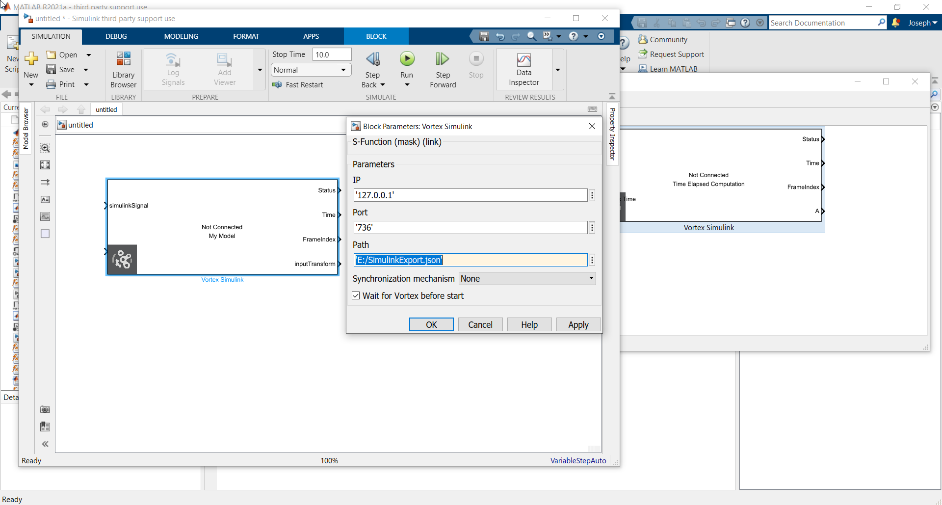
- Press OK.
- The Vortex block will be updated with the inputs and outputs specified in the .json file. These will match those contained in the Simulink extension in Vortex. The name underneath the 'Not Connected' text, will be the Model Base Name specified in the corresponding Simulink extension.
- This Vortex block can now be placed inside whatever Simulink model you are working with, and the inputs and outputs hooked up as desired.
This completes the configuration of the Vortex block in Simulink.
Running the Simulation
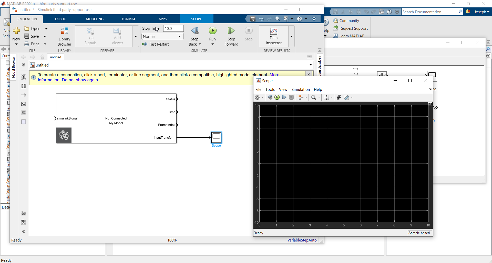
To demonstrate information being transferred from Vortex, we will add a scope block to the Simulink model.
- Search for scope in the Library browser.
- Add the block to the Simulink model.
- Connect the inputTransform port of the Vortex block to the scope. This will allow us to see that data is being transferred from Vortex to Simulink.
- Double click on the scope block to bring up the visualization of the data.
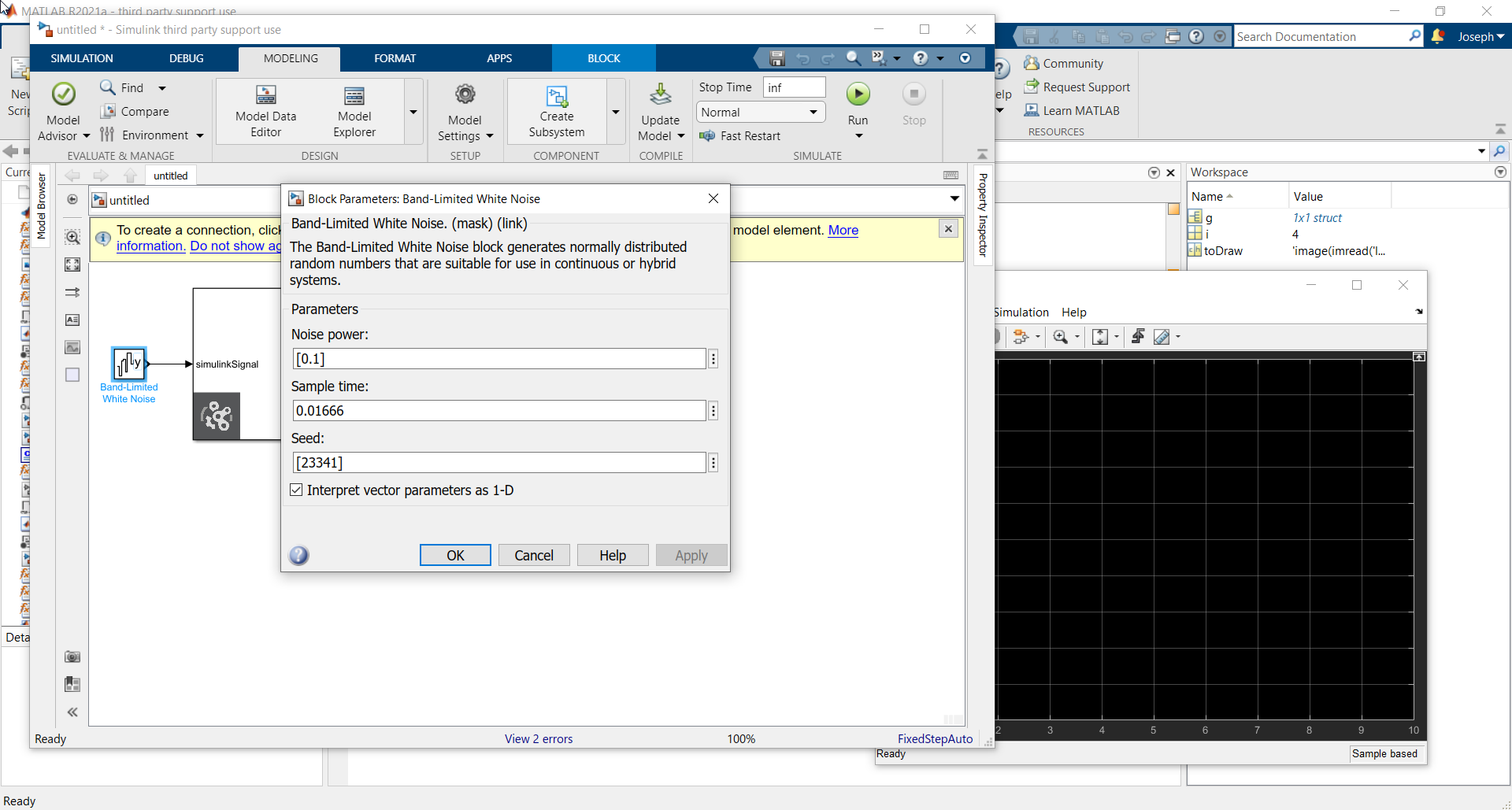
To demonstrate information being transferred to Vortex, we will add a white noise generator block to the Simulink model.
- Search for Band-Limited White Noise in the Library browser.
- Add the block to the Simulink model.
- Connect the simulinkSignal port of the Vortex block to the Band-Limited White Noise block. This will allow us to see that data is being transferred from Simulink to Vortex.
- Double click on the Band-Limited White Noise block, and set the Sample time to 0.01666s
- Click the Modeling tab in Simulink.
- Click the Model Settings button.
- To keep the Simulink model running indefinitely, set the Stop time to 'inf'.
- If you wish to synchronize Simulink with Vortex, we must also set the Solver selection Type to Fixed Step and the Fixed-step size to the same as Vortex (default 0.01666).
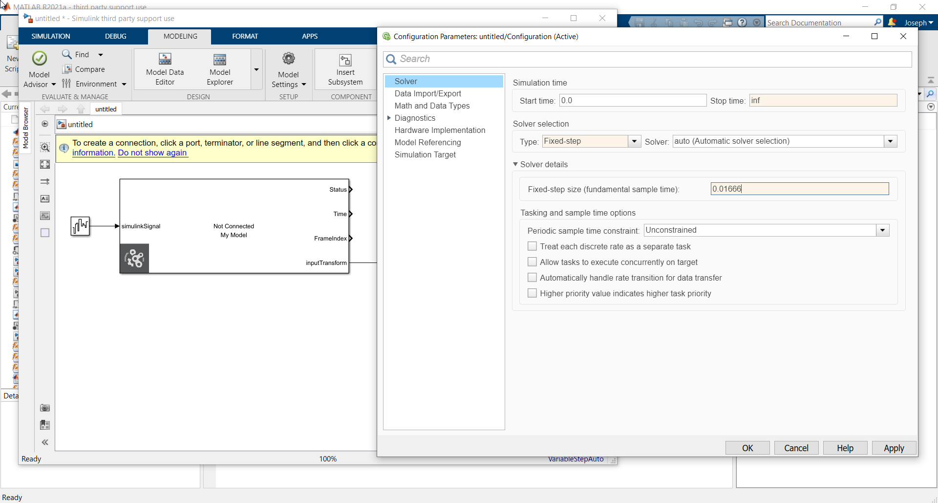
- Click OK and return to the model.
- Now, ensure that your Vortex application is open, and the Mechanism which contains the Simulink Extension is loaded.
- In Simulink, click Run to run the model.
The Vortex block in Simulink should now displayed 'Connected' rather than 'Not Connected'.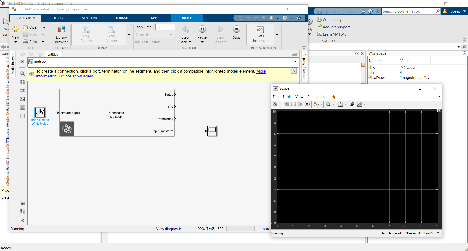
- In Vortex, click the plotter button in the lower right corner of the viewport, and drag the simulinkSignal variable into it. This will allow us to see the signal coming from Simulink.
- Click play in Vortex to begin the simulation.
- Moving the part in Vortex will cause the lines on the scope to change, as the values of the global transformation are received from Vortex.
- With time the signal in the Vortex plotter will change randomly, as the white noise is generated in Simulink and sent to Vortex.
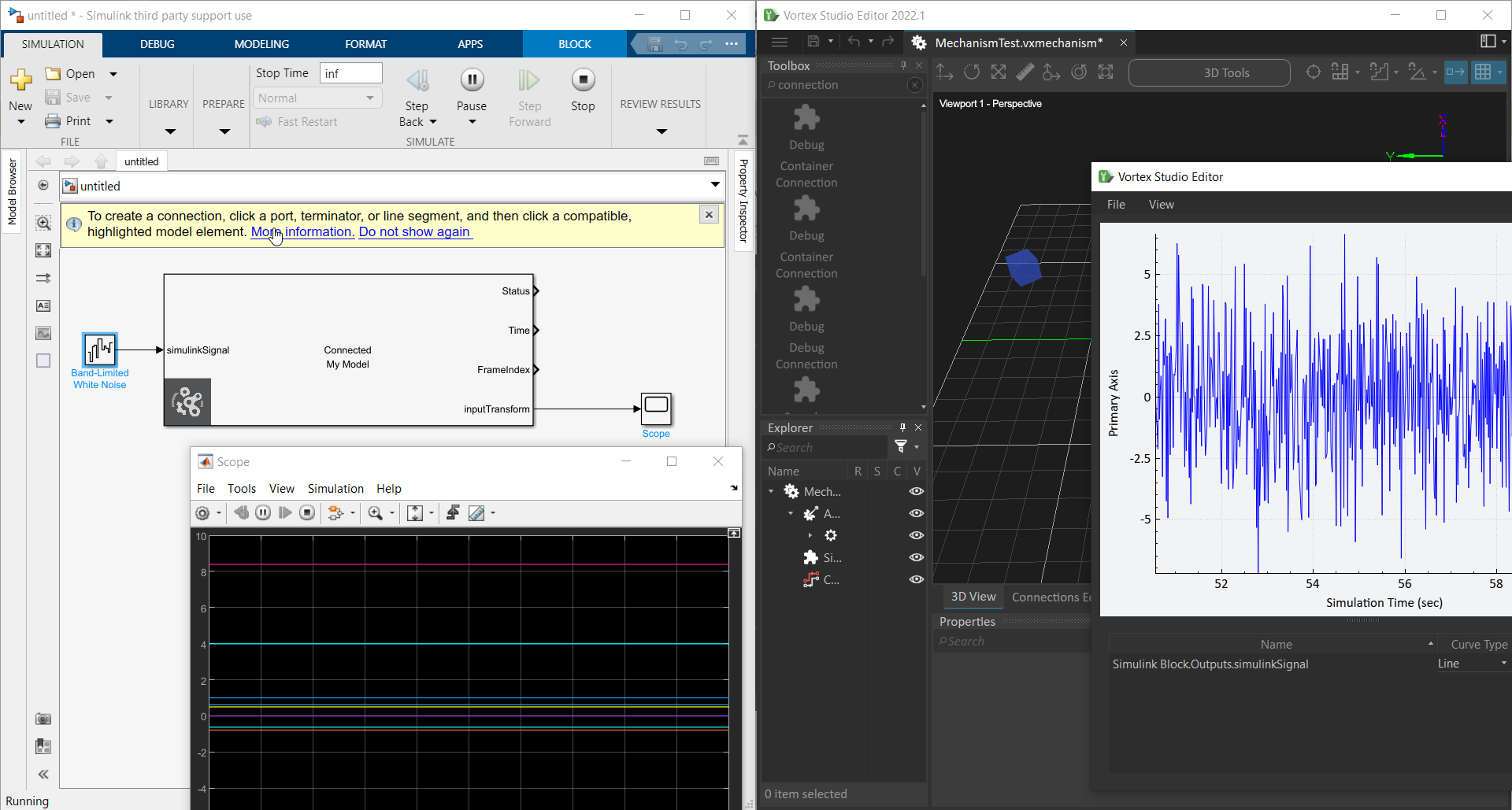
With this, the link between Simulink and Vortex is established, and information can be transferred between them.
Some other useful features of the Simulink Block extension are:
- Multiple Simulink blocks can be used in a single Vortex simulation, though they must all have unique model base names.
- Integer, Unsigned Integer, Short Integer, Unsigned Short Integer, Double, Vector3, Color and Transform are the Vortex data types available for transfer.
- The Simulink Block extension context menu also has an 'import configuration' option. This allows you to choose a .json file with the configuration you like and apply it to a Simulink Block extension without having to edit the variables everytime. Should you require many Simulink Block extensions to have the same input and output variables.