Modular Vehicles Tutorial 3: Adding Tire Models
In Vortex Studio, Tire Models are critical to the physical accuracy and drivability of vehicles. Without this extension, the material table is used to evaluate the friction between the tire and ground, which does not account for the complexities of the tire slipping and deforming on the ground.
In this tutorial, we're going to be adding Hard Ground models to simulate dry asphalt as well as and icy road and Soft Ground models to simulate sand and mud. We're also going to map these materials on a terrain in a scene for our vehicle.
Prerequisites
Modular Vehicles Tutorial 2: Creating a Vehicle from a Template
Adding a Tire Type to the Mechanism
Adding Tire Types allows to have different Tire models assigned to different wheels. In the case of this tutorial, we'll only have one tire type since the 8 wheels of the LAV are the same.
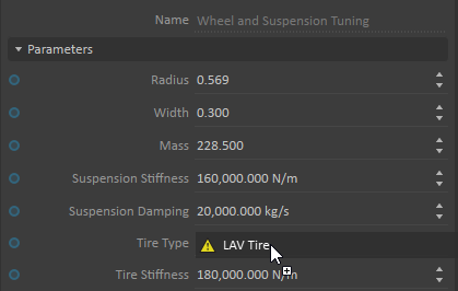
- From the Tire Model section of the Toolbox, insert a Tire Type.
- Rename (F2) it "LAV Tire".
- Assign the Tire Type to the Tire Type Input of the Wheel and Suspension Tuning VHL.
Adding Tire Models
In this section, we're going to add Tire Models to our Tire Type and map those models to materials in the Material Table.
Adding Hard Ground Tire Models
For this tutorial, we'll be using Coulomb Tire Model for hard ground types. Please refer to the Tire Models Documentation page for a detailed explanation of the models as well as tuning guidelines.
- Under Tire Type Collection, right click on the previously created LAV Tire. Select Add Tire Model Coulomb.
- This should add a Tire Model labeled "Coulomb". Rename it "Road"
- In the Properties of this model, under Inputs/Ground Materials, add a material. Rename it "Road". Add another material names "default"
Create two additional Tire Models for Wet Road and Ice.
The material named "default" should only be added to one of the models. You will get an error message otherwise.
Set values for the properties listed in the table below for each models:
Property Road/Default Wet Road Ice Compliance 4.000e-08 4.000e-08 4.000e-08 Friction Coefficient Longitudinal 0.900 0.650 0.350 Static Friction Coefficient Longitudinal 1.200
1.200 1.200 Friction Coefficient Lateral 1.000 0.700 0.400 Static Friction Coefficient Lateral 1.200 1.200 1.200 The compliance (reciprocal of stiffness) of the material listed in this table is added to the Tire Compliance of the wheel adapter when calculating the overall stiffness of the tire on the ground. On hard ground, the former is generally much smaller than the latter.
Adding Soft Ground Tire Models
To simulate sand and mud, we're going to use the Bekker soft ground model.
- Under Tire Type Collection, right click on the previously created LAV Tire. Select Add Tire Model Soft Terrain.
- This should add a Tire Model labeled "Soft Terrain". Rename it "Mud".
- In the Properties of this model, under Inputs/Ground Materials, add a material. Rename it "Mud".
- Repeat with a new Soft Ground Tire Model and assign it to Sand.
Set values for properties listed below:
Property Mud Sand Inputs Compliance 4.000e-08 4.000e-08 Lateral Force A 4.000 4.000 B 0.500 0.500 Pressure Sinkage n 1.000 1.000 kc 5.700 8.000 kphi 1,900.000 2,500.000 Rolling Resistance Base Coefficient 0.040 0.020 Speed Factor 6.000e-05 6.000e-05 Speed Exponent 2.000 2.000 Slip 5.000e-05 5.000e-05 Shearing External K 1.150 1.150 c 1.150 1.150 phi 31.500 31.500
Mapping Ground Materials to a Test Track
In this section, we're going to create a scene where we can test the driving of the vehicle in each ground materials modeled in the previous section.
- From the Vortex Studio Main Menu, create a new Scene.
- From the Environment section of the Toolbox, add a Terrain From File...
- In the resulting window, Click on the Browse... button of the Terrain File field. Select TestTrackTerrain.vxgraphicgallery found in
<Demo Scenes>\Environment\VehicleTestTerrain\Graphic. - Under the Material section, set the Default Material to Road.
- Make sure the Mapping Strategy is set to By Node.
Use the Add Rule button to create the set of rules listed in the table below:
Name (RegEx) Materials .*Asphalt.* Road (.*Asphalt_Wet.*)|(.*Gravel.*) Wet Road (.*Ice.*)|(.*Snow.*) Ice .*Mud.* Mud .*Sand.* Sand - From the Simulation section of the Toolbox, add a Material Table to the Scene.
- In its Properties, under Parameters, browse the Material table file and select Defense vehicles_material.vxmaterials found in
<Demo Scenes>\Scenario\Defense Vehicles Scene. - Insert the vehicle in the scene by using Basics > Mechanisms From Files. Place it on one of the tracks.
- Start (F7) the simulation. Using the Explorer, select one of the wheels from the Wheel Collection. In the Outputs of its Properties, make sure that the Ground Material Name field shows the right material.
- Test the vehicle on different tracks and observe the effects of materials on the driving.