Mechanisms
- DEVOPS
 Mechanisms play a very important role in Vortex® content, as they contain the link between the dynamics objects and the rest of the simulation.
A mechanism contains assemblies, parts, constraints, and extensions for simulation.
The figure below indicates where mechanisms are located in the Vortex hierarchy.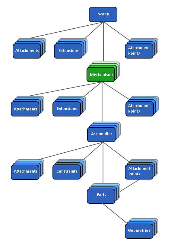
Working with Mechanisms
To start building a mechanism, first you import a 3D model, create assemblies, and connect parts and geometries to 3D models.
From there, you can fuse two assemblies together by attachment points on them in the Assembly editor. In addition, you can insert extensions to add logic.
If you need to create special access to some properties in your mechanism, you can expose a set of properties as a VHL interface. The exposed parameters are then available in the Connection Editor at the scene level, or can be accessed outside of Vortex (for example, in an external simulator or game engine or database).
You can also make connections between Vortex objects and VHL parameters, extensions, etc.
Finally, you can test the mechanisms in the Mechanism editor.
Working with VHL Interfaces
The Vortex® High Level (VHL) Interface simplifies your workflow by exposing only a defined subset of the mechanism's input values, output values, and parameterization values so that a systems integrator can modify these values without coding or scripting.
Additionally, non-modifiable properties and their respective values and parameters are protected during modification, testing, and validation stages. Effectively, this makes a clear separation between mechanisms and scenes.
VHL properties are comprised of the following:
- Inputs: These are properties used to operate the mechanism during simulation.
- Outputs: These are properties used to get and read information about the outcomes of the simulation.
- Parameters: These are the properties that define or specify mechanism behavior or used to control and condition the way a mechanism is simulated. They are typically agreed upon and provided at the design stage of the development of a given mechanism.
Opening an Existing VHL Interface
This procedure explains how to load a existing interface in the VHL Interface Editor.
- If you are not already in the Mechanism editor, open the mechanism containing the VHL Interface.
- From the Explorer panel, open the VHL Interfaces folder and locate the Interface you want to open.
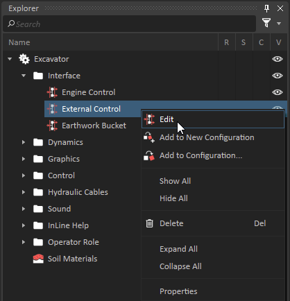
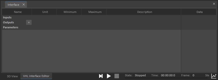
Right-click the Interface and select Edit from the context menu. The VHL Interface Editor loads in the main window (where the 3D View usually appears).
Each VHL target can only be bound to a single property.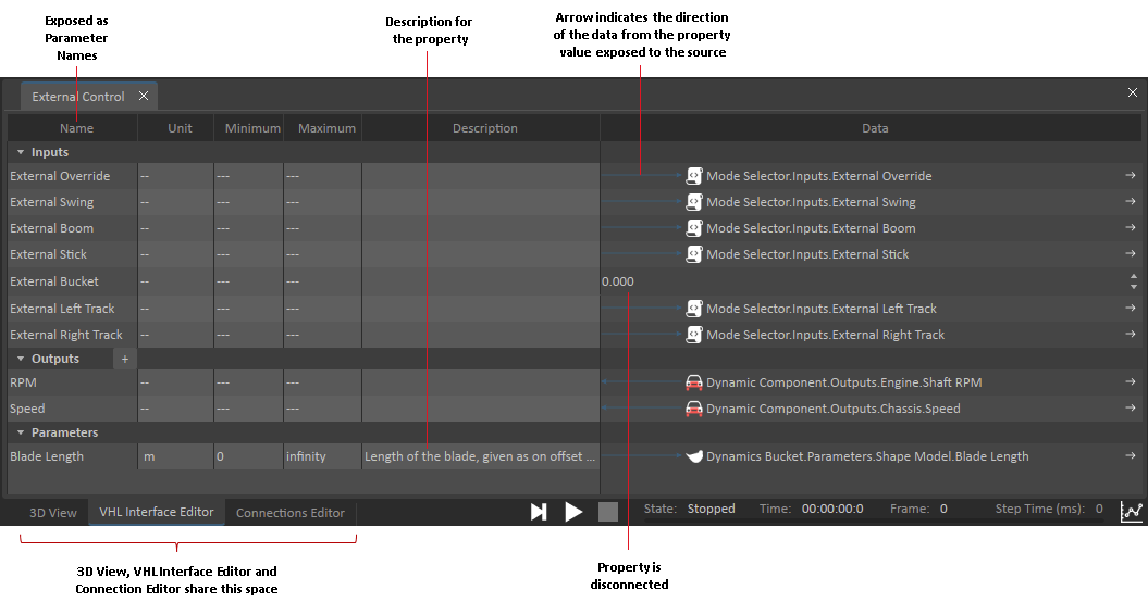
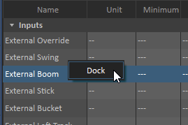
- To undock the VHL Editor, right-click anywhere on the VHL Editor and select Undock. This allows you to see the contents of the 3D View and the VHL Editor at the same time and move it around the workspace. To dock it again, right-click inside the VHL Interface Editor window and click Dock.
Creating a New VHL Interface
The VHL Interface Editor allows you to expose properties in the VHL.
You can also use it to rename properties and add meaningful descriptions for each property.
- If you are not already in the Mechanism editor, either open an existing mechanism or create a new one.
- Select Simulation in the Toolbox.
- Double-click VHL Interface. The VHL Interface Editor appears.
- In the Explorer tree, click any object that contains properties (parts, constraints, controllers, wheel components, and collision geometries). Their properties appear in the Property panel on the right.
From the Property panel, drag and drop the property you want to expose onto either the Input, Output, or Parameters section of the Interface Editor.
Read-only input and parameter properties cannot be exposed in the VHL Interface Editor.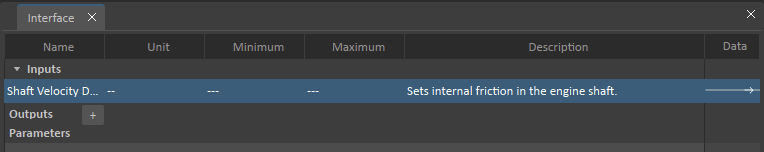
- Now you can perform any of these tasks to customize your exposed parameter:
- By default, the exposed parameter uses the name of the internal property. To use a different name, double-click on the Name cell and type the new name.
- To add a description for the parameter, double-click on the Description cell and type the description. You can press the Enter or Tab key to finish editing.
- You can add minimum and maximum values for the parameter in the appropriate column. A exposed parameter can only be set the range value of the minimum and maximum value.
- To break the link between the VHL Interface and the source of the property, hover over the arrow in the Data column of the property you want to disconnect. When you see the trash can icon, click on it. The parameter still appears in the VHL Interface Editor, but the link to the reference of the data has been disconnected.

- To connect a property to an existing parameter (for example, if its link was broken), drag and drop the property onto the Data column of the target property's row.
- To delete the entire parameter entry from the Interface, select the row you want to delete and press the Delete key.
- Additionally, you can add Outputs to the Interface Editor by clicking the + button next to Outputs heading.
- In the resulting drop-down list, select the type of data for this new output (e.g., Integer, Boolean, String). An output of that data type is added to the table, where you can edit its details.