Parts
- DEVOPS
Parts represent rigid bodies that can be connected together with joints and can collide with each other and the environment.
For information on modeling the shapes of parts, affecting collision forces, and modeling fluid interaction forces such as buoyancy, drag, and lift, please refer to Collision Geometries.
A Part can be added to an Assembly and contains a set of Collision Geometries.
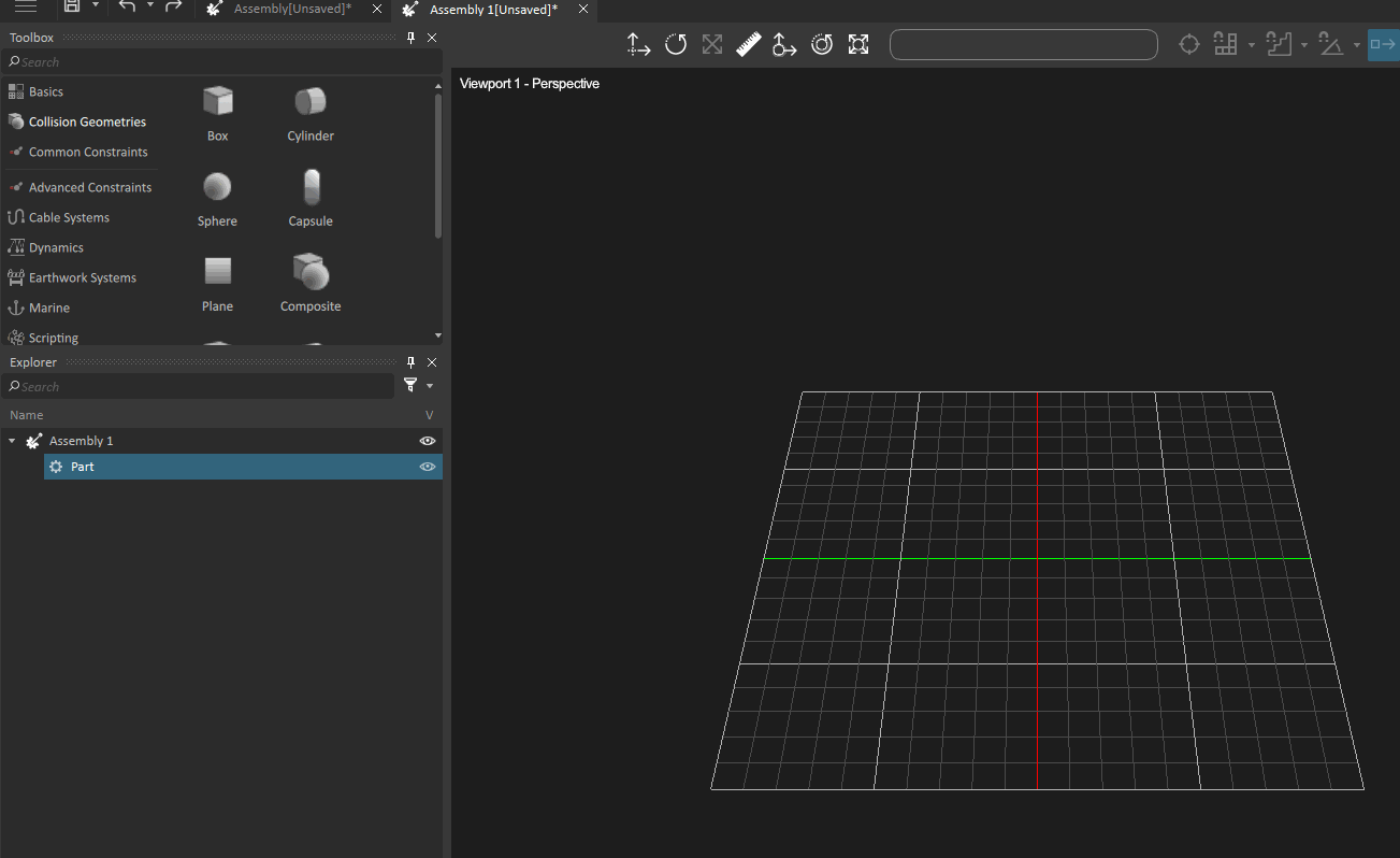
The figure below indicates where parts are located in the Vortex® hierarchy.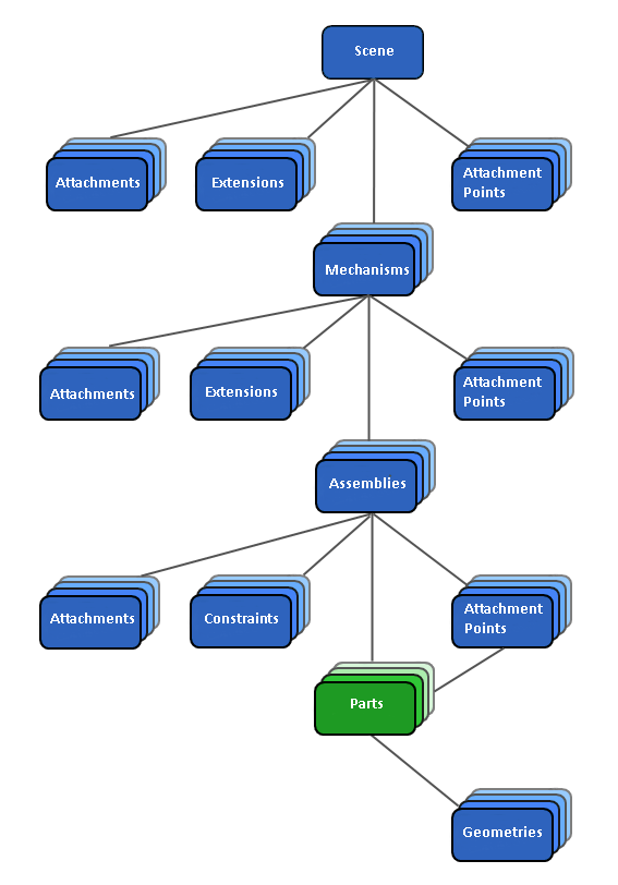
A part has three control types: animated, dynamic, and static. Control types dictate how the part interacts with other parts. The control type of each part can be changed in the corresponding part's Properties panel.
This table shows which control type has which effect on a Part. Is the part affected by forces, e.g., when colliding with another part? Or, can the part move at all? For example. a part reacts to forces when the Control setting is Dynamic. Forces can be applied to a part by constraints, contacts, and gravity. In this setting, the part can move.
| Control Type | Can Move (has velocity) | Affected by Force | Example |
|---|---|---|---|
| Animated | Yes | No | Windmill blades, conveyor belt, drawbridge |
| Dynamic | Yes | Yes | Door on hinge, bouncing ball, articulated arm |
| Static | No | No | Terrain, horizontal or vertical planes |
Editing Parts and Collision Geometries Efficiently
In order to make it easer to work on a part and its collision geometries, a part can be viewed in its own reference frame. For more details, see Viewing a Part in its Reference Frame
Building Parts from a 3D Model
Once you have created the assembly and added your 3D model, you can start adding parts.
This procedure assumes you have set up an assembly and imported a graphic asset from which you built the parts. If that is not the case, follow the instructions under Assemblies first.
Follow these instructions for each part you want to create:
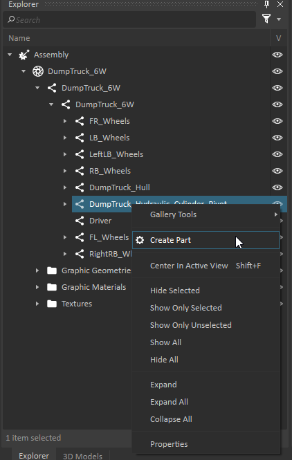
- In the Explorer Panel, expand the tree to locate the node that you want to use to generate the geometry. As you move around the tree you can see in the 3D View that various nodes on the reference model are being highlighted.
- Right-click on the node and select Create Part from the context menu.
- Right-click on the part in the Explorer Panel and select one of the following from the context menu:
- Create Best-Fit Geometry > Best-Fit to let Vortex® decide which primitive geometric shape fits the best.
- Create Best-Fit Geometry > <Shape Name> to pick a specific primitive geometric shape to use.
- Create Best-Fit Geometry > Triangle Mesh... to generate a triangle mesh.
- Create Best-Fit Geometry > Convex Mesh... to generate a convex mesh.
- Create Best-Fit Geometry > Convex Mesh Decomposition... to select a convex mesh decomposition method and specify its parameters.
If you chose best-fit, Vortex will select the shape that most closely approximates the 3D model from the list of primitive shapes only (convex and triangle meshes are never used). For example, in the image below, the wheel on the left at the front appears with a box collision geometry shape and the wheel on the right at the front appears with a triangle mesh. You can also see the wheel at the back which has no part or geometry at all.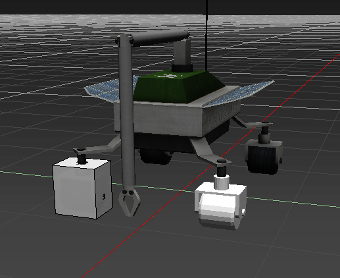
Triangle and convex meshes are useful when there is a part whose shape does not match primitives such as spheres and boxes, but there is no support for collision geometry between two meshes. In addition, meshes are costly to compute during a simulation, so it is recommended to use primitive geometry shapes whenever possible.
You can now see the newly generated geometries in the tree. By default, they are set up for collision only, but you can change this to buoyancy or drag geometries by following the instructions under Changing the Geometry Type (Collision, Buoyancy, Drag, Lift).
Creating Parts and Geometries Manually
You can add a collision, buoyancy, and drag force geometry to your part which provides a specific set of properties.
Buoyancy and drag geometries are typically used to set fluid interaction properties when creating parts: for example, for subsea simulation environments.
Creating geometries from a 3D model at the Assembly level is by far the best option; however, sometimes you need to create parts and add geometries to them manually. In this case, you can follow the instructions in this section.
- If you are not already in the Assembly editor, either create a new part or load an existing one.
- From the Toolbox, drag the Part to the 3D View. A Part will be created at the drop location and it will be added to the Assembly.
You can also drag and drop the Part in the tree, or simply double-click on the Part in the Toolbox - From Toolbox, drag the desired shape type you want for the part into the 3D View, or double-click it (see Geometry Shape Types for a list and description of the available types). The Collision Geometry will be added to the selected Part. You can also double-click the Collision Geometry, or drop it in the explorer tree.
- Select the part from in the Explorer panel.
- In the part's Properties panel, select the Geometries tab.
- Select the box for the desired collision type. (For example, Buoyancy.)
After you have added geometries in the 3D View grid, you can modify them by, e.g., assigning a material to the selected collision geometry, edit their shape or reposition and reorient them. Please refer to Collision Geometries for more details.
Modifying the Position and Orientation of Parts
You can choose to transform the parts in your assembly using either of these methods:
- By using the Transform tools in the 3D View
- By editing the values directly in the Properties panel for each part
Performance Optimization Techniques
In simulations that involve many parts, simulation performance can become an issue, due to too high time consumption in the physics engine. One way to address this issue is to adaptively simulate only a sub-set of parts in the simulation, using one of the two techniques below.
Part Sleeping
While simulating scenes, parts that are at rest are considered to be asleep.
Putting parts to sleep is an optimization technique to reduce computation time for parts that are significantly affecting the simulation.
For a part to fall asleep it must be at rest for a given minimum number of simulation steps (the Threshold Steps property). A part is considered at rest if its speed and acceleration stay below a given threshold value, defined by the Auto-sleep properties.
To set the sleep thresholds:
- Select the part you want to edit in the Explorer panel.
The part's properties appear in the Properties panel.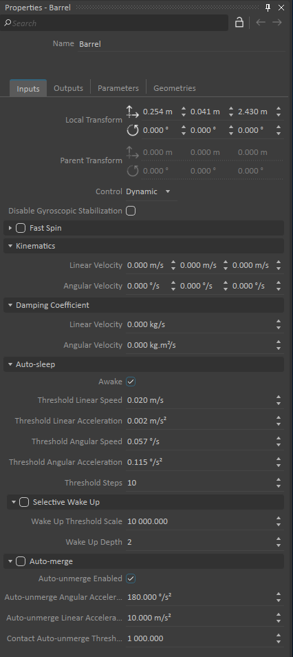
- You can edit the values under the Auto-sleep section:
- Threshold Linear Speed
- Threshold Linear Acceleration
- Threshold Angular Speed
- Threshold Angular Acceleration
- Threshold Steps
- You can also edit the Selective Wake Up sub-section within Auto-sleep. These parameters allow you to more precisely control the conditions over which a sleeping part can be awoken. Select the Selective Wake-Up box to enable this sub-section.
- Wake Up Threshold Scale: Wake Up Thresholds are defined as scaled versions of the Auto-sleep thresholds. If the sleeping part is connected to another part through a constraint or contact, the speeds or the accelerations introduced by the connection must be larger than the auto-sleep threshold multiplied by the "Wake Up Threshold Scale".
- Wake Up Depth: This field represents the number of connected parts that can be awoken. If a sleeping part is awoken, all other connected part(s) up to the Wake Up Depth value will be awoken, as well. For example, if Wake Up Depth is set to 1, only the set of parts directly connected to the original part will wake up.
To activate the part's center of mass visualization, right-click the eye icon next to the part's Visibility Toggle column, then select the Center of Mass. COM is shown as a colored sphere in the 3D View. The colors represent the following:
- Red: The part is dynamically simulated.
- Dark Red: A part is asleep.
- Orange: A group of parts is merged and its position represents the position of the encompassed center of mass of the group.
- Green: A group of merged parts is asleep.
There are four event-driven ways to wake a part:
- When a part comes in to contact with another part. For example, at collision.
- When an external force is applied to a part. For example, environmental factors such as wind.
- When a constraint between two parts is modified. For example, changing the motor desired velocity.
- When the user enables the Awake property in the Assembly Editor.
Part Auto-merging
The Auto-merge feature is another technique to optimize the simulation time by decreasing the number of individual parts that are simulated. This technique can be used when your simulation contains several objects in contact that are not expected to move relative to each other.
The technique compares the relative motion of two parts connected by at least one contact (i.e., a contact exists between them). For such connected parts, if the relative speeds and relative accelerations are lower than the Auto-sleep thresholds, the two parts will be merged together. As a consequence, the number of simulated parts will be decreased by one, reducing the size of the constraint system and thus improving the performance. If the two merged parts are in contact with a third one, this one can also be merged with the two previous ones. This process repeats itself for all the parts in contact forming a set of merged parts. Notice that there is no limit to the number of parts that can be merged together.
Considering physical fidelity, merging parts results in the rigid body encompassing the mass property of each of the parts resulting in the same dynamics behavior. The total linear and angular momentum is also respected. Collision detection is fully maintained with the parts' individual collision geometries.
One of the most interesting characteristics of this feature is that a set of merged parts can move. The Auto-merge feature includes the possibility to automatically unmerge under certain conditions.
To set the Auto-merge parameters:
- Select the part you want to edit in the Explorer panel.
- Edit the following fields:
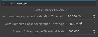
- Check the Auto-merge box to enable the feature.
- Auto-unmerge Enabled: Enables automatic unmerging for auto-merged parts.
If set to true, auto-merged parts will automatically unmerge when any of the following conditions are metA constraint incident to this part was removed, added, or otherwise modified.
An external force or torque was added to the part (Note that Fluid Interaction adds external force on a part at each frame).
The part's linear/angular acceleration exceeds the "Auto-unmerge Angular/Linear Acceleration Threshold"
A contact occurred with the part and at least one of the Auto-sleep thresholds scaled by the "Contact Auto-unmerge Threshold Scale" was exceeded.
- Auto-unmerge Angular Acceleration Threshold: The part is demerged if the angular acceleration exceeds this value.
- Auto-unmerge Linear Acceleration Threshold: The part is demerged if the linear acceleration exceeds this value.
- Contact Auto-unmerge Threshold Scale: When contact occurs with the auto-merged part, it is demerged if the relative linear/angular acceleration or velocity exceeds the related Auto-sleep threshold multiplied by this value.
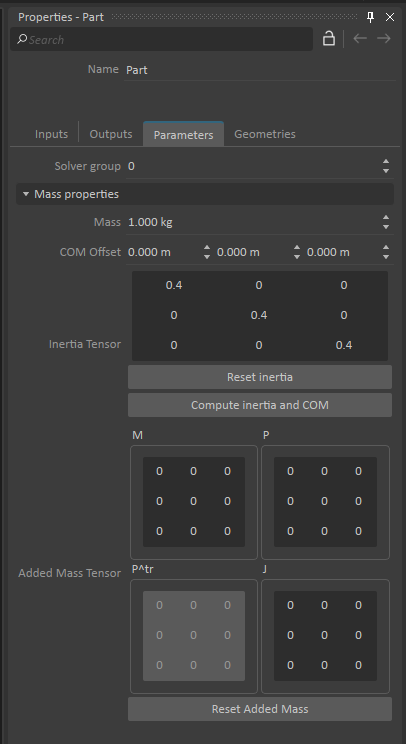
Editing the Part's Mass Properties
When setting up parts, it is important to define their mass properties to enable accurate and stable simulations.
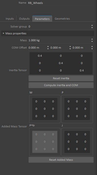
In the Vortex® Studio Editor, a part's Mass Properties represents the sum total of each geometry's values for these settings:
- Mass
- COM (Center of Mass) Offset
- Inertia tensor (see Inertia Tensors for technical information about inertia tensor values)
You can set these properties directly in the Properties panel or use the Mass Properties control in the 3D View:
Select the part in the Explorer panel.
The Properties panel now displays the part's mass properties in the Parameters tab.
To display the part's inertia in the 3D View, right-click the eye icon in the part's Visibility Toggle column. Make sure that Inertia is checked to see the inertia of the object modeled on screen.

Enter the total Mass for the part. If the Mass Properties control is visible in the 3D View, you can see how changing the mass affects the size of the sphere: the larger the mass the smaller the sphere.
Warning The default value for Mass is 1.000 kg, so you must set the correct value for the part you are creating. If you do not enter the correct value, the default will be used and may not produce the expected results during the simulation.
Set the COM Offset for the part. This is an offset to the origin position of the part. You can manually set this property if you know the exact values. However, it is recommended to use the Mass Properties control in the 3D View for setting the COM Offset, especially if you have multiple geometries defined in your part.
Set the Inertia tensor for the selected part. The inertia tensor matrix is represented in the Properties panel as a 3x3 table which you can edit manually if you know the exact values. However, it is recommended to use the Mass Properties control in the 3D View for setting the inertia tensor, especially if you have multiple geometries defined in your part.
Setting the Mass Properties in the 3D View
The Properties panel for a part includes the Mass Properties section, which displays the Mass value, the X, Y, and Z values for the COM Offset, and a 3x3 matrix that represents the Inertia tensor.
You can set these values manually, but it is much easier to achieve the desired effect by manipulating the control in the 3D View.
In the Explorer panel, right-click the eye icon in the part's Visibility Toggle column. Make sure that Inertia is checked to see the inertia of the object modeled on screen.
Special 3D tools are available when a Part is selected. You can use the following 3D Tools to manipulate the mass properties of the part:
- Move COM offset

- Rotate inertia

- Resize inertia

- Move COM offset
If you have multiple geometries, you can get Vortex® to automatically compute the inertia tensor and center of mass (COM) values by clicking the Compute inertia and COM button in the Properties panel.
If you want to return to the default values, click the Reset inertia button in the Properties panel.
Configuring the Added Mass
Added mass is the inertia added to an object as a result of accelerating or decelerating through a volume of surrounding fluid as it moves through it.
Added mass is not caused by drag effects but is a result of having to move fluid out of the way. Added mass, or virtual mass, depends only on the pressure on the body from the fluid, along with intrinsic and geometric properties of the body.
In Vortex®, you can set the added mass by using the Added mass tensor which is a 6 x 6 matrix.
You must have a part open in the editor.
In the Explorer panel, click on the part to reveal its Mass Properties in the Properties panel.
In the Added Mass Tensor, enter the values appropriate to the part. M is the mass added, P, the propeller tensor, is the coupling between the linear movement and the angular movement, and J is the inertia added. \(P^T\) is the transpose matrix of the propeller(P) matrix.
Specifying the Initial Velocity of Parts
In rare occurrences, parts need to have an initial velocity immediately at the start of the simulation. This can be done as follows.
- Select the part you want to edit in the Explorer panel.
The part's properties appear in the Properties panel. - You can edit these values for each coordinate in the Kinematics section:
Linear Velocity: meters per secondAngular Velocity: degrees per second