Earthwork Systems Tutorial 2: Creating an Earthwork Zone
In this tutorial, users will learn how to use the earthworks tools in Vortex® Studio to create a zone with interactable earthwork physics.
Prerequisites
You must have Vortex Studio and the Vortex Studio Samples installed to be able to complete this tutorial. Additionally, you must have completed Earthworks Training Module 1: Creating Bucket & Blade Extensions
Establishing the Scene
To begin, we will open a pre-existing scene to create an earthworks zone in. First, open the Excavator Workshop scene, found by default under the path: ...\Vortex Studio Content <VERSION>\Demo Scenes\Scenario\Excavator Scene\ExcavatorWorkshop.vxscene.
- Zoom in on the scene and approach the center of the pit in the middle of the scene.
- Using Mechanism From Files, insert ExcavatorWorkshop.vxmechanism saved in the last tutorial.
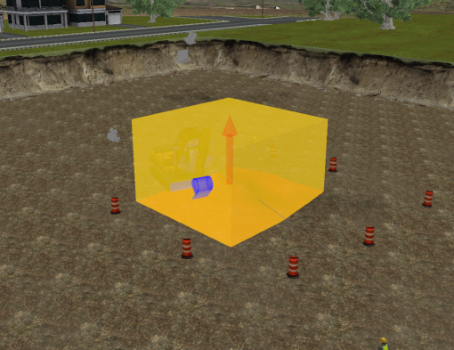
- In the Toolbox, under Earthwork Systems, add an Earthwork Zone to the scene.
- Set the Local Transform of the Earthwork Zone to -5, 0, -9 m.
- Under the properties of Dynamics, under Earthwork Zone, check the box that says "Diggable".
- Under Earthwork Systems in the Toolbox, add a Soil Materials extension to the Earthwork Systems folder.
- Move and rotate the excavator so that it is positioned to dig in the Earthwork Zone.
Refining the Earthwork Zone Graphics
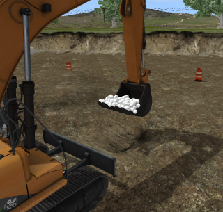
If you start the simulation and start digging with the excavator, you'll notice that the materials that have been dug don't have a material assigned, so it appears white. Thus, next we must assign the disturbed earth a material.
- Under the folder Earthwork Systems, under Soil Dust, select Graphics.
- Next, under the extension Earthwork Zone, select Graphics.
- In the properties, under Inputs, select PitSides_Texture as the Graphics Material. This will make it so the disturbed earth texture is no longer simply white.
- Finally, under the folder Earthwork Systems, under Soil Particles, select Graphics.
- Under Inputs, click the three dots next to SSM Material, and select PitSides_Texture from the Explorer. This will make it so the small particles in the dirt no longer be white.
- Now, under Particle Models, increase the Size to 1.
- Under Geometry, click the three dots and select Geo_Rock_Geometry_001, which is found under the Gallery - Rock Particles Geometries graphics gallery in the Explorer.
- Click on the three dots next to Material, and select Loam_SSM, which can be found in the Materials subfolder under the Loam graphics gallery.
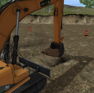
- Start the simulation. Begin digging with the excavator and observe the fully functional earthworks zone in action.
Adding Dust Particles
- Select the Dynamics extension under Soil Dust in the Explorer panel to open its Properties panel.
- Under Inputs, set the following values:
- Dust Emission Probability: 2%
- Minimum Impact Strength: 350
- Maximum Impact Strength: 400
- Minimum Impact Velocity: 1 m/s
- Select the Graphics extension of Soil Dust.
- Assign the Soil_dust (Loam > Materials) to the Graphics Material field.
- Set the following values in the listed fields:
- Particle Lifetime (in seconds): 5 s
- Particle Size Change: (0.5, 6, 0)
- Particle Alpha Change: (0.5, 0, 0)
- Particle Alpha Fade Interval: 0.15 s
- Particle Color Start: (118, 84, 52, 255)
- Particle Color End: (163, 115, 77, 255)
- Particle Color Change: 0.1
- Particle Angle Start Range: (0, 360, 0)
- Emission Rate: 1.000
- Spray Cone Theta Range: (0.2, 120, 0)
- Spray Cone Phi Range: (0, 120, 0)
- Spray Linear Speed Range: (0, 0.07, 0)
- Spray Angular Speed Range: (0.2, 0.8, 0)
- Gravity Acceleration: (0.08, 0.1, 0.1)
- Under Parameters, change the Particle Limit to 1000.
- Save the scene.