Hook and Loop Groups
- DEVOPS
Before creating a Hook group or a Loop group, one or more mechanisms must have already been created. These mechanisms should have an attachment point (defined at the assembly level) at each point that will function as either a hook or a loop.
The two types of extensions can either be added to the same mechanism or to separate mechanisms. They can also be created at the scene level.
To create a Hook Group or Loop Group:
- Select Dynamics in the Toolbox.
- Double-click Hook Group or Loop Group to add it to the scene or mechanism.
- Configure the relevant fields in the respective Properties panels, described below.
Hook Group Properties
The Hook Group extension defines attachment points as hooks, where you can view information on the constraints that bind those hooks to their associated loops.
The Hook group's Properties panel contains the following fields.
Inputs
- Enable: Selecting the checkbox next to "Inputs" enables the hook extension. If unchecked, this extension no longer offers any anchoring points as valid hooks, and any hooking constraints associated with this extension are removed. This bypasses Always Allow Unhooking.
- Hook: When checked, the Hook group will attempt to initiate the hooking process as soon as it is in range of a valid Loop group. If this box is unchecked, the unhooking process is attempted. For more information on these processes, see Hooking Process below.
- Always Allow Unhooking: A hook and a loop which are in the "Hooked" state cannot be unhooked unless this box is checked.
Note: All loops must be attached before breakage can occur.
- Enable Hooking Display: Select this box to visualize the Hooking Display.
- Hooking Display Size: Sets the size of the attachment point, in meters.
- Hooking Display colors: The colors, set in RGB and transparency (alpha), of the attachment points are customizable based on their state. The available color states are:
- Hooking Display Out-of-range Color
- Hooking Display In-range Color
- Hooking Display Attracting Color
- Hooking Display Attached Color
- Hooking Display Detachable Color
- Breakable Inputs
- Enable Breakage: Specifies whether the hook will break when the tension surpasses the Maximum Tension value.
- Break After X Count: Determines the cumulative number of frames where the tension is greater than Maximum Tension after which the hook will break.
- Maximum Tension: Specifies the maximum tension supported by the hook before it breaks.
- Break Now Points: Each anchoring point will have a corresponding row in the Break Now Points section. By selecting the Break Now box during simulation, the cable attached to that point will break.
Outputs
- In Range: This box appears checked when a valid Loop group is close enough to hook with this Hook group.
- Hooking: Indicates whether this Hook group is currently engaged in the hooking process. For more information on this process, see the Hooking/Unhooking section below.
- Hooked: This box appears checked when all the hooks in this Hook group have completed the hooking process.
- Detachable: This field will appear selected if its related Hook group has the capacity to be unhooked.
- Target Mechanism: Displays the mechanism that contains the Loop group currently being targeted for hooking by this Hook group.
- Centroid: Displays the coordinates of the centroid for this group's anchoring points.
- Has Broken: This box appears selected during the frame when a previously attached cable ruptures.
- Broken Position: Displays the position of the broken cable during the frame that it ruptures.
- Active Constraints: During simulation, this field is populated with constraints corresponding to each hook in the group, one row for each anchoring point. See Hooking Constraints below.
- Hooked to Default: During simulation, this container is populated with the hooks in the Hook group., one row for each anchoring point. The checkboxes corresponding to the hooks attaching to the Default Attach Point (see below) appear checked.
- Hooking Display: Increasing the size of the Anchoring Points parameter adds a corresponding row to this output. If using a Hooking Display extension, this output must connect to its input.
During simulation, these outputs are viewable in the Hook group extension:
- Enabled: This box is selected if the constraint is currently active, whether attracting or attached.
- Hooking Point: Displays the attachment point of the hook.
- Attach Point: Displays the attachment point of the target loop.
- Hooked to Default: This box is selected if the constraint is between a hook and the Default Attach Point.
- Attached: This box is selected if the associated hook and loop have completed the hooking process and are in the "Hooked" state.
- Force: The amount of force being exerted by the constraint, in newtons.
- Distance: The distance between the associated hook and loop, in meters.
Parameters
- Prevent Crossing: When selected, the hooks will only pair with loops in a sequential order, which is helpful to prevent hooks from crossing over each other. When using this feature, ensure that all hooks and loops are assigned to their groups in a circular order.
- Anchoring Points: See Anchoring Points below.
- Hooking Constraints: Once a valid Loop group comes within range, the Hook group extension creates a constraint for each hook and its target. These constraints allow three degrees of positional freedom, and two degrees of angular freedom (on the X- and Y-axes). As a result, the hook and loop cannot rotate relative to each other around the Z-axis, emulating the behavior of a hook in a loop. You should ensure at content creation that the Z-axis of your attachment point is pointing in the expected direction. The following fields are available:
- Friction Coefficient: Coefficient of friction of the coordinates.
- Limit Coordinate 1: The upper limit in radians for rotation about the X-axis. The lower limit is the negative of this value.
- Limit Coordinate 2: The upper limit in radians for rotation about the Y-axis. The lower limit is the negative of this value.
- Attract Stiffness: The stiffness of constraint coordinates when attracting.
- Attract Damping: Damping constant of constraint coordinates when attracting.
- Attract Max Force: Maximum force of constraint coordinates when attracting.
- Attach Distance: The distance at which a hook and loop pair that are hooking will become hooked, binding them together.
- Detach Force: The maximum force allowed in a constraint for unhooking to be allowed.
- Default Attach Point: If this field is populated by an attachment point, any surplus hooks in the Hook group that are left over after each loop in the target Loop group is paired with the provided attachment point instead.
- Snapback Parameters: See Snapback Parameters.
Loop Group Properties
The Loop Group extension defines attachment points as loops, where you can view information on the constraints that bind those loops to their associated hooks.
Inputs
- Enable: Selecting the checkbox enables the loop extension. If unchecked, this extension no longer offers any anchoring points as valid loops.
- Hooking Range: Distance for a hook to become in range of this associated loop group.
- Show Range:
- If the checkbox is checked, a range sphere is shown with the actual size specified in Hook Range input.
- If the checkbox is not checked, a target sphere is shown with the size specified in Hooking Display Size input.
- Hooking Range Extension: Hooking Range is extended by this length to have a Hook Group stay in range for longer when it's about to leave the hooking area.
- Enable Hooking Display: Select the checkbox to visualize the Hooking Display.
- Hooking Display Size: Sets the size of the attachment point, in meters.
- Hooking Display Out Of Range Color: The color indicates the Hook Group is out of range with the Loop Group. For more details, refer to Hooking Process.
- Hooking Display In Range Color: The color indicates the Hook Group is in range with the Loop Group. For more details, refer to Hooking Process.
- Hooking Display Attracting Color: The color indicates the Hook Group is in hooking phase with the Loop Group. For more details, refer to Hooking Process.
Outputs
- Enabled: This box is selected if the constraint is currently active, whether attracting or attached.
- In Range: This box appears checked when a valid hook group is close enough to hook with this look group.
- Hooking: Indicates whether this hook group is currently engaged in the hooking process. For more information on this process.
- Hooked: This box appears checked when all the loops in this look group have completed the hooking process.
- Centroid And Range: The centroid for this group's anchoring points.
- Hooking Display: Increasing the size of the Anchoring Points parameter adds a corresponding row to this output.
Parameters
- Anchoring Points: See Anchoring Points below.
Anchoring Points
Anchoring points define which attachment points are used as hooks or loops.
A hook will only consider a loop to be a valid target if the hook and loop have at least one label in common. However, if a hook or loop has no named labels, that hook or loop is considered to be a wild card and will disregard the labels of its potential targets.
Note When adding multiple anchoring points to a group, they should be defined in a circular sequence (e.g., clockwise). The same sequence should be used for each Hook and Loop group to ensure that Prevent Crossing performs correctly.
To add an anchoring point:
- In the group's Properties panel, under Parameters, increase the value of Anchoring Points > Size.
- In the empty Anchoring Points field that appears, click the browse button and select an attachment point of an existing mechanism from the Explorer panel or 3D view.
- Click the check mark.
- Under Labels, adjust the Size field to add the desired number of labels, if any.
- In the resulting label field(s), add a custom label name.
Hooking Process
When the hook constraints of a Hook group ultimately link to a Loop group, the process is called "hooking" and follows the stages described below.
- In Range
The Hook group waits for a valid Loop group to be close enough, as defined by the Hooking Range parameter of the Loop group. As long as this condition is true, both groups are flagged as in range. - Hooking
When a Hook group is in range of a Loop group, and its Hook input is selected, the Hook group enters the Hooking phase.
During this phase, the constraints exert a force bringing each hook and loop pair toward each other. The parts associated with the hooks and loops will not collide with the parts of their partner. The angular limits of the constraint are also applied, forcing the hook and loop into an orientation that satisfies those limits.
Once a hook and loop pair are Hooking, the process can only be cancelled by disabling the Hook input. Until that happens, neither group is considered a valid hooking partner for any other group. - Hooked
Once a hook and loop are close enough, as defined by the Attach Distance parameter in the Hook group, they will attach each other. This holds the hook and loop to each other with a stronger force than during Hooking. Once each hook or loop in a group is in this state, the group's Hooked output box is selected. - Unhooking
Whenever the Hook input is disabled for a Hook group that is in the Hooked state and has Always Allow Unhooking checked, unhooking occurs. All hooks in the Hook group will cancel their Hooking or Hooked states.
In the case where Always Allow Unhooking is not checked, unhooking can only occur if there is no tension between the hook and loop.
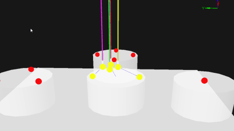
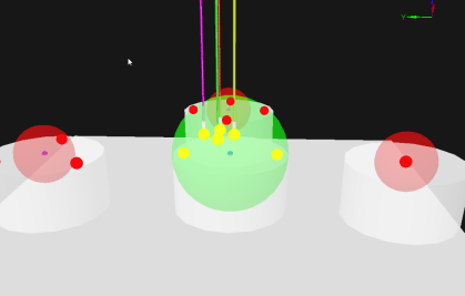
Hooking Display
The Hooking Display extension allows you to visualize the Hook and Loop Groups' centroid and attachment points.
Note Starting with Vortex Studio 2019b, adding a Hook Group or Loop Group extension automatically adds a Hooking Display extension as a sub-extension. The Hooking Display extension exists as a stand-alone extension for backwards compatibility purposes with previous versions of Vortex Studio.
In order to see the display visualization, right-click in the 3D View and select Debug Display > Accessory. For a pre-created sub-extension, the Hooking Display input will already be connected to Hook or Loop Group's Hooking Display output. If you created your own Hooking Display extension, you must make a connection to the desired output.
|
|
| Hooking Display of Hook Group Accessory | Hooking Display of Loop Group Accessory |
|---|
In the Properties panel, configure the following fields:
- Visible: Keep this box selected to have the Hooking Display visible in the 3D View.
- Hooking Display: This section is where you can see the position of each anchoring point and its color during a simulation. Increase the Size field here to add Hooking Display attachment points. If the Hooking Display extension is connected to a Hook or Loop Group, these rows are governed by the Anchoring Points parameter.
The colors, set in RGB and transparency (alpha), of the attachment points are customizable based on their state. The available color states are:
- Hooking Display Out-of-range Color
- Hooking Display In-range Color
- Hooking Display Attracting Color
- Hooking Display Attached Color
- Hooking Display Detachable Color
These last two states are not applicable in Loop Groups because, when attached, the loop shares its position with its corresponding hook.