Earthwork Utilities
- DEVOPS
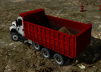
Learn about specialized soil utilities to help manipulate and monitor soil.
A number of specialized soil utilities are available to help manipulate and monitor soil.
- The Soil Bin defines a container (truck bed, ship hold, storage bin, etc.) into which soil material can be poured. When soil material is present in the bin, it can also be dug into and removed.
- The Soil Layer is a versatile tool that can add soil within the bounds of an existing soil bin or earthwork zone. It is used to pre-fill soil bins, create soil piles and layers, and can also be used to bury items underground.
- The Soil Emitter, as its name implies, emits soil particles at a user-defined rate, with specific soil properties. It can be used to simulate a concrete bucket, for example.
- The Soil Culling Geometry can cull (erase) soil particles on contact. It is mostly used to simulate a drop zone, for example a hopper.
- The Soil Mass Sensor measures soil mass within certain boundaries. It is mostly used to measure spilled soil particles.
- The Soil Culling Monitor works only in conjunction with the Soil Culling Geometry, and measures soil mass that come into contact with it. It is mostly used to measure spilled soil particles.
- Special Deformable Soil Effects add extra visualization options for more soil information.
Soil Bin
The Soil Bin extension could be considered a sort of movable Earthwork Zone. It is used to simulate truck beds, ship holds, and any other construct that is intended to receive or contain soil. It is initially empty (though it can be pre-filled via the Soil Layer tool), and it supports soil dumping and digging (once soil has been deposited in it).

Before adding a Bucket extension to a mechanism, the latter should be first created with all the relevant parts, constraints and logic. Make sure that a part is created for the Soil Bin. The mechanism can be static or dynamic: a static mechanism must have all its parts set to the static control type. If the mechanism contains dynamic components, such as a vehicle system, collisions between these dynamic components and the Soil Bin extension must be disabled through collision rules.
When creating the collision geometries for the soil bin part, you can use primitives (such as boxes) to model the container. Those will be used for the interaction with other parts in the simulation, such as the bucket of the excavator. However, you will also need to create a separate triangle mesh collision geometry which represents the entire soil bin container, sidewalls and bottom included. This triangle mesh will be used later on to define the shape of the soil bin in the Soil Bin extension. To prevent any impact on simulation performance, you should disable collision detection with this triangle mesh by clearing any checkmark in the Enabled option under the Collision detection section of the collision geometry's Properties page.

To add a Soil Bin extension:
- In your mechanism, select Earthwork Systems in the Toolbox.
- Double-click Soil Bin to add one to your mechanism, or drag it into the 3D View.
A new folder with a Soil Bin icon appears under the mechanism in the Explorer Panel. It contains one dynamic extension and two graphic ones, plus a connection container; in the 3D View, you can now see their corresponding accessories.
- Dynamics Soil Bin: This extension defines the physical properties and shape of the Soil Bin extension.
- Graphics Soil: This extension controls the visual appearance of the soil contained within the Soil Bin extension.
- Graphics Particle Culling Box: This extension cull particles, emitted by the Particle Spray extension of a bucket, once they reach the bottom of the soil bin. This prevents visual particles from appearing below the soil bin.
- Connections: These are the data connections between the various components. They are set automatically.
After adding the soil bin to the mechanism, the next step is to link the soil bin's part to the dynamics extension and link the soil bin's graphic node to the graphics soil extension. Then the respective extensions are positioned in the mechanism (e.g., a dump truck) in order to accomplish their purposes. For example, the bounding box defined in the Dynamics Soil Bin extension needs to precisely fit in the body of the container which will receive the soil, e.g., the bed of a dump truck.

Attaching the Dynamics Soil Bin to the Soil Bin Part and Collision Geometries
From the Explorer panel, click the Dynamics Soil Bin extension under the Soil Bin folder. The Dynamics Soil Bin properties appear in the Properties panel.
Under the Parameters section:
- Click the Browse button, then
 in the Bin Part reference field. The Select Soil Bin Part dialog box appears.
 - From the Explorer panel of your mechanism, go into the assembly, then locate and click on the part that you've set up for the soil bin of the mechanism.
- The Soil Bin part's name appears in the Select Bin Part dialog box. Click the Confirm button.
- The Soil Bin part's name now appears in the parameter box, and the accessory position is now relative to the soil bin part's origin.
- Click the Browse button, then in the Bin CG reference field. The Select Bin CG dialog box appears.
- From the Explorer panel of your mechanism, select the collision geometry which represents the entire soil bin geometry. Click the Confirm button.
The name of the collision geometry now appears in the Bin CG reference field.
Note The collision geometry specified as Bin CG is used by the extension to sample the soil bin container. It is mandatory that it represents the entire geometry of the soil bin container, therefore using a triangle mesh for this purpose is strongly advised. To prevent any impact on simulation performance, the triangle mesh can be disabled in the collision detection by clearing any check mark in the Enabled option under the Collision detection section of the collision geometry's properties.
Attaching the Soil Bin's Graphics Soil to the Soil Bin Node
From the Explorer panel, click the Graphics Soil entry under the Soil Bin folder. The Graphics Soil properties appears in the Properties panel.
- Under the Parameters section, click the Browse button in the TerrainNode reference field. This nodes serves the same purpose as in the simple or generic bucket, that is, to sample the shape of the initially empty bucket. The Select TerrainNode dialog box appears.
- From the Explorer panel of your mechanism, go into the Graphics Gallery, then locate and click on the graphic node of the soil bin.
- The Soil Bin graphic node's name appears in the Select TerrainNode dialog box. Click the Confirm button.
The Soil Bin graphic node's name now appears in the parameter box and the Graphics Soil accessory box follows the soil bin's graphic node.
Configuring the Dynamics Soil Bin Extension
After connecting all the parts and nodes to the Soil Bin's extensions, you can see that the accessories are now clustered around the soil bin's origin.
The Dynamics Soil Bin extension's accessory is a colored box similar to the one defined on an Earthwork Zone. However, the soil bin accessory also provides four sets of parallel lines (green on one side, and red on the other) that act as guides as you position the accessory on the soil bin of the 3D model.

The outer lines define the boundary vertices of the dynamics height field, and the inner lines define the vertices which are adjacent to the boundary. They can be used as guiding aids during placement of the dynamics soil bin extension.
The red lines will always be perfectly aligned with the faces of the bounding box of the dynamics soil bin. The outermost red lines have to be placed exactly on the top of the side walls of the container which form the soil bin (e.g., the bed/box of a dump truck). The innermost red lines on the other hand have to be placed inside and on the bottom of the container (not on the side walls). This is to ensure that the outermost vertices of the height field are initially at a higher location than their adjacent inside vertices. When pouring soil into the soil bin, soil will then accumulate properly inside the bin and climb up until the height of the boundary vertices is reached.
After the red lines have been placed, the green lines need to be placed in an analogous way at the front and the back of the container. Note that due to the discrete nature of the dynamics height field which has square cells (that is, equally spaced vertices in local x and y direction), the green lines will not perfectly follow the faces of the bin's bounding box as is the case for the red lines. Instead they will jump from one place to another depending on the size of the box. This will make sure that cells in the dynamics height field always remain square. It is therefore easier to start fitting the red lines and fitting the green lines last, as the red lines will remain at their chosen location while placing the green lines.
From the Explorer panel, click the Dynamics Soil Bin entry under the Soil Bin folder. The Dynamics Soil Bin properties appear in the Properties panel.

- Local Transform: Modify these values to position the Dynamics Soil Bin accessory within the soil bin model. Alternatively, use the Move/Rotate manipulators in the 3D View to change the values.
- Parent Transform: Not used.
- Clear: If this input is selected, any soil present within the soil bin will be removed. This input can be used by a script to empty the soil bin at runtime.
- Shear Strength: Sets the shear strength of the soil within the Soil Bin, making it stronger or weaker. Reducing this value will make the soil slip easier, reducing the angle of repose. Also, less force will be needed to cut through the soil. See Shear Strength in Earthwork Zone for more.
- Flow Velocity Scale: Scales how fast the soil in the soil bin flows.
- World Transform: This is used to drive the graphic extensions. It is set automatically.
- Dimensions: Defines the dimensions of the soil bin, and is used to drive the Graphics Soil extension. It is set automatically.
- HeightField: This output is used to drive the Graphics Soil extension. It is set automatically.
- Particles: This output is used to drive the Graphics Soil extension. It is set automatically. The Mass output shows the mass of soil currently in the soil bin. It can be used by a script or displayed via a HUD.
- Parameters:
- Material: This is the dynamics material assigned to the surface of the dynamics height field. Useful for tuning contact behavior when objects collide with the soil surface in the soil bin.
- Bin Part: This is the part for the Soil Bin, that was attached in the previous step.
- Bin CG: This is the collision geometry for the Soil Bin, that was attached in the previous step.
- Dimensions: Modify these values to resize the Dynamics Soil Bin accessory to match the soil bin model. The Dynamics Soil Bin accessory should tightly wrap the soil bin part. The 3D Resize manipulator should always be used to modify this property.
- Approximate Cell Size: This is the preferred size of the cells that divide the height field within the soil bin. See Cell Size in Earthwork Zone for more.
- Spilling Enabled: If the field is deselected, the soil will remain in the soil bin. Note that this can cause unrealistically steep soil slopes at the soil bin's rim.
Note The accessory box has to be placed such that the boundary of the height field (outer rows and columns of vertices), marked by green and red lines, coincides with the sidewalls of the soil bin when seen from the top. The next rows and columns of vertices, marked by the inner set of green and red lines, should lie in the inside of the soil bin. It is possible, that the chosen approximate cell size has to be adapted to reach this configuration. The lines displayed in the Editor are meant to assist you in correctly placing the extension. The red lines will always lie exactly on the corresponding faces of the bounding box, while the green lines will perform jumps to produce square height field cells in the simulation. So, it is recommended to place the red lines first, and then place the green lines. This way, the already correctly placed red lines will not be affected by the manipulations done to place the green lines (resize of bounding box or refinement of approximate cell size). If you are having difficulty matching the dimensions of the accessory to the soil bin wall, try changing the Approximate Cell Size parameter and trying again. For example, decreasing the cell size will slightly narrow the gap between the inner and outer lines, making it easier to fit narrower soil bin walls.
Adding Collision Detection Rules to the Dynamics Soil Bin
When using the Dynamics Soil Bin extension with a dynamic vehicle, the extension requires additional collision detection rules to create a realistic and stable simulation.
Once you have created the dynamic vehicle and attached the Dynamics Soil Bin extension, create additional collision detection rules:
- Between the mechanism and itself.
- Between the Dynamics Soil Bin extension and the Mechanism.
- Between the Dynamics Soil Bin extension and the Dynamic Component of the Vehicle Systems.
Make sure that the collision detection check box is not selected for each.
Configuring the Graphics Soil Extension
The Graphics Soil extension defines the height of the particles inside the soil bin. It is placed and resized automatically to match the shape and location of the Dynamics Soil Bin extension, if the proper terrain node is selected.
From the Explorer panel, click the Graphics Soil entry under the Soil Bin folder. The Graphics Soil properties appear in the Properties panel.

- Visible: If selected, the soil particles appear in the 3D viewport.
- Cast Shadow: If selected, the soil particles will cast shadows (this is computation intensive).
- Receive Shadow: If selected, the soil particles will receive shadows cast by other objects.
- Graphics Material: This points to a graphics material within a Graphics Gallery, that determine the general appearance of the soil particles (texture, reflectivity, etc.).
Note To allow flexibility at runtime, you can expose this parameter via a VHL so that the operator can select the correct graphics material for the specific scenario. See Working with VHL Interfaces.
- Local Transform: Modify these values to position the Graphics Soil accessory.
- Parent Transform: Makes the Graphics Soil accessory follow the Dynamics Soil Bin. It is set automatically.
- Terrain Upscaling: Modify the terrain upscaling between the input and output zones when displacing soil.
- Particle Spreading: The particles which are travelling on the surface of the dynamics height field, and which are transferred to the Graphics extension from the Dynamics extension, are wrapped by the Graphics height field. The Particle Spreading parameter defines how much the volume of a single particle will be spread out on the graphics height field's surface. Setting this to the value X will affect all height field cells which are touching the circle with radius "X * particleRadius", placed at the center of the particle. Also refer to Inflation Factor below.
- Blend Range: This value (in meters) determine the blend interval when displaced soil is blended.
- Blend Bias: This value (in meters) determine the height offset when displaced soil is blended.
- Blend Enable: Selecting this box activates soil blending.
- Blur Enable: Selecting this box activates blurring when soil is in motion.
- Minimum Height Deformation: Minimum height deformation relative to the original soil surface to apply the graphics material on the deformed area (in meters). This parameter is used only in subtract mode.
- Rising Factor: This value help to reduce graphical artifacts when the height field mesh matches the original mesh. Rising Factor determines the height offset to apply to the height field mesh, in meters.
- Terrain Node: This is the graphic node of the soil bin model. Set the Size field to 1 and, in the resulting row, use the Browse buttons to select the desired node from the Explorer panel. If more nodes are necessary, increase the Size field and repeat.
- ShowParticles: This is a debugging option to see the particles received by the height field. It should not be used in the final build of a simulator.
- Inflation Factor: This parameter defines how much of the particle volume should be considered for the wrapping effect. It is used in the "Particle wrapping stage" in which the graphics height field is lifted off in order to wrap soil particles which travel on the surface of the dynamics height field. Setting the inflation factor to 1.0 will lift the height field as high as needed to account for 100% of the volume of the soil particles. A value of 0 will turn the wrapping feature off.
- Blend Mask:Specifies a black and white texture file used to determine the initial dug state of the soil. White portions of the texture file indicate an area where the material initially appears as dug, while black areas appear untouched.
- Update Rate (sec): This field is used to reduce the amount of CPU cycles used for rendering graphics by setting an amount of time to wait between each update (in seconds). For instance, if the update rate field is set to 1.0, the graphics will be updated once every second.
Configuring the Graphics Particle Culling Box Extension
Typically the Graphics Particle Culling Box should be positioned such that it creates a tight fit with the container of the soil bin.
Its Z-axis should point upwards out of the soil bin. Any particle emitted by a Particle Spray extension which crosses either the bottom face or any of the side faces will be removed from the simulation. This way, when emptying a bucket into the soil bin, those visual particles will be removed before they can travel through the sides of the container.
From the Explorer panel, click the Graphics Particle Culling Box entry under the Soil Bin folder. The Graphics Particle Culling Box properties appears in the Properties panel.

- Visible: Not used.
- Local Transform: Modify these values to position the Graphics Particle Culling Box accessory.
- Parent Transform: Makes the Graphics Particle Culling Box accessory follow the Dynamics Soil Bin. It is set automatically.
- World Transform: This output provides the world space transformation of the Particle Culling Box.
- Dimensions: Modify these values to resize the Dynamics Soil Bin accessory to match the soil bin model. The Dynamics Soil Bin accessory should tightly wrap the soil bin part. Alternatively, use the Resize manipulator in the 3D View to get it as close as possible.
Soil Layer
This is a versatile tool that can add soil within the bounds of an existing soil bin or Earthwork Zone. It is used to pre-fill soil bins, create soil piles, and can also be used to bury items underground.

The Soil Layer extension provides the means to add loose or rigid layers of soil to Earthwork Zones and Soil Bins. Layers can also be added below the initial surface of Earthwork Zones which allows for detailed specification of the compactness of the soil at simulation start. Furthermore, by adding soil to Soil Bins at simulation start, truck beds or other containers can already be prefilled at the beginning of a scenario. This can be useful in scenarios which focus specifically on unloading operations, such as the unloading of a dump truck by a hydraulic excavator.
To add a Soil Layer extension:
- In your scene or mechanism, select Earthwork Systems in the Toolbox.
- Double-click Soil Layer to add one, or drag it into the 3D View.
Soil Layers can also be added exclusively to a Soil Bin. This is essential in situations such as a dump truck use case, where you would only want soil in the bed of the truck and not in the surrounding terrain.

To add a Soil Layer to a Soil Bin:
- In your mechanism, find the desired Soil Bin in the Explorer panel.
- From the Toolbox, select Earthwork Systems > Soil Layer, and drag and drop it under the Soil Bin.
Configuring the Soil Layer
From the Explorer panel, click the Soil Layer extension. The Soil Layer properties appear in the Properties panel.
- Soil Surface CG: This is the collision geometry representing the surface of the added layer.
- Relative Density: Relative density of the added soil layer (in percentage of the density of the main soil). This is only available if the Diggable box is checked.
- Diggable: Specifies whether the added layer is diggable soil or defines the undiggable bottom of the zone.
The following figure shows an arrangement of a Soil Bin with three Soil Layers, each represented by the surface of a collision geometry (CG). Each layer adds soil to the Soil Bin with different relative densities as shown on the left. The layers are stacked. As such, every layer will add soil on top of the layer immediately below it until the bottom of the Soil Bin is reached as indicated in the figure.

This additional figure shows two diggable and one non-diggable Soil Layer in an Earthwork Zone created on a File Terrain. The non-diggable layer adds an undeformable rock surface to the zone into which no tool can dig. Diggable layers above the surface of this embedded hard rock will deposit soil but only until the top of the rock layer. For any surface point of an Earthwork Zone or a Soil Bin, the topmost non-diggable layer at this point marks the height below which no deformation can occur.

The layers added to a Soil Bin or an Earthwork Zone can be visualized during simulation in the Vortex Studio Editor using the accessories of the bin's or zone's Dynamics extension. The accessory color codes the relative density (compactness) of the soil in green for lowest to blue for highest density. The relative density visualization is updated at runtime and will change accordingly when cutting or compacting the soil with a tool, as shown in the following figure:

As can be seen in this figure, the Soil Layer extension can be conveniently used to model a layer of hard and compacted soil (shown in blue) above looser soil (shown in bright green). In such a simulation, an excavator will have to apply a considerably higher force in order to penetrate and excavate the hard crust before gaining access to the softer soil beneath.

To bury an item in the ground, first make it into a separate mechanism with a single part and collision geometry. The part should be set as Static in the Assembly. For best visual interaction with the soil, make the CG slightly smaller than the graphic of the mechanism so that the simulated soil will not have any gap around the buried object.
Place it at the desired location under the surface, but within the Earthwork Zone volume. Add a Soil Layer tool and point the Soil Surface CG to the collision geometry in the mechanism. Make sure the Diggable checkbox is cleared.
The item can now be uncovered and reburied, though it won't be possible to dig under it (the columns under the height field must remain continuous).
Soil Emitter
This tool emits soil particles at a user-defined rate. The soil properties are defined, as always, by the global Soil Materials extension.
With the emitter, soil can be dynamically added to ongoing simulations. This enables modelling of advanced processes in construction, mining and bulk material handling, such as the operations of concrete buckets, soil conveyor systems, stackers, and spreaders.

The Soil Emitter is a soil particle generator which adds particles to an ongoing simulation based on user-specified emission control inputs. The emission frequency as well as the shape and location of the emitter can be specified. The emitter defines an ellipse whose size can be controlled. Particle emission happens at random locations within this ellipse. Furthermore, the radius of the emitted particles as well as their initial linear velocity after creation can be specified through inputs. An output gives access to the mass of soil generated since simulation start.

To add a Soil Emitter extension:
- In your scene or mechanism, select Earthwork Systems in the Toolbox.
- Double-click Soil Emitter to add one, or drag it into the 3D View.
From the Explorer panel, click the Soil Emitter extension. The Soil Emitter properties appear in the Properties panel.

- Local Transform: Modify these values to position the Soil Emitter (communicated visually via an accessory in the 3D Viewport).
- Parent Transform: This can be used to connect the Soil Emitter to another object.
- Linear Velocity: This is the linear velocity of the emitted particles along the emission direction (X-axis), in meters per second.
- Particle Radius: This is the radius of emitted particles, in meters.
- Emission Frequency: This value defines the number of emitted particles per second.
- Emitter Disc Radius U: This is the radius of the emitter ellipse in U direction, in meters. Particles are emitted at random locations on an ellipse. The ellipse is normal to the emitter's X-axis and located at the emitter's center. It is spanned by the two local axes U and V, which coincide with the emitter's Y- and Z-axes respectively. This parameter defines the size of the ellipse along U.
- Emitter Disc Radius V: This is the radius of the emitter ellipse in the V direction, in meters. Particles are emitted at random locations on an ellipse. The ellipse is normal to the emitter's X-axis and located at the emitter's center. It is spanned by the two local axes U and V, which coincide with the emitter's Y- and Z-axes respectively. This parameter defines the size of the ellipse along V.
- World Transform: Not used.
- Emitted Soil Mass: This output is the total mass of soil particles emitted by the Soil Emitter since the start of the simulation.
In order to facilitate tuning of soil emitters, soil particles in any Earthwork Systems simulation, generated either through emitters or by cutting soil with a tool, can be visualized for debugging purposes. Particles in the vicinity of a soil surface (e.g., a Soil Bin or Earthwork Zone) are color coded according to their relative density as shown in the following figure. Particles with high relative density are displayed in blue and particles with low relative density are displayed in green. To activate the debugging visualization, enable the accessory of the Dynamics component in the Soil Particles extension.

Soil Culling Geometry
This tool can cull (erase) soil particles on contact. It is mostly used to simulate a drop zone, for example a hopper.
As opposed to the ability to generate soil particles via the Soil Emitter, the Soil Culling Geometry allows for removal of such. With this extension, soil particles which collide with a given geometry can be removed (culled) from the simulation immediately. The Soil Culling Geometry can be combined with a Soil Culling Monitor in order to retrieve the mass of the culled particles.

Through dynamic removal of soil particles, advanced processes in mining, construction and bulk material handling can be modeled in a very efficient way. This includes soil particles being removed once loaded or pushed into hoppers or crushing stations. Furthermore, spill of material outside of designated drop zones can be monitored and used for operator performance metrics as shown in the figure above.
To add a Soil Culling Geometry:
- In your scene or mechanism, select Earthwork Systems in the Toolbox.
- Double-click Soil Culling Geometry to add one, or drag it into the 3D View.
From the Explorer panel, click the Soil Culling Geometry extension. The Soil Culling Geometry properties appear in the Properties panel.

- Assembly: Soil particles colliding with the selected assembly will be removed from the simulation. Obviously, an assembly needs to be present in the scene for this tool to work. To select an assembly, click the Browse button, then . In the resulting window, select an assembly from the Explorer panel.
- Culling ID: The ID of this culling geometry. This can be used together with a Soil Culling Monitor to read the mass of soil culled by culling geometries with a specific ID. It is useful for recording operator stats during training missions, e.g., amount of soil spilled.
Soil Mass Sensor
This tool measures soil mass within certain boundaries. It is mostly used to measure spilled soil particles.
See Adding a Soil Mass Sensor.
Soil Culling Monitor
This tool measures soil mass that come into contact with it. It is mostly used to measure spilled soil particles.
To add a Soil Culling Monitor:
- In your scene or mechanism, select Earthwork Systems in the Toolbox.
- Double-click Soil Culling Monitor to add one, or drag it into the 3D View.
From the Explorer panel, click the Soil Culling Monitor extension. The Soil Culling Monitor properties appear in the Properties panel.

Culled Soil Mass: Total mass of soil particles (in kg) culled by culling geometries with the monitored "Culling ID" since the start of the simulation.
Culling ID: The Culling ID of the Soil Culling Geometry extensions which are being monitored. When soil particles are culled by culling geometries with the provided ID, their mass will be included in the output Culled Soil Mass. This is useful for recording operator stats during training missions, e.g., amount of soil spilled.
Deformable Soil Effects
The following special effects grant you extra visual information about deformable soil.
To add a soil effect:
- Right-click on the graphics soil in the Explorer panel (e.g., Soil Bin > Graphics Soil, or Earthwork Zone > Graphics).
- Select Material Modifiers and select one of the effects described below.
- Add Erosion Flow Modifier: Effect that renders erosion on height fields. This effect computes flowing velocities using the heights. These velocities are used to move the pixels on the height field. Adding a soil erosion effect adds a new child extension named Erosion Flow with the following inputs:
- Visible: Toggling this box enables or disables the effect.
- TriPlanar Texture Mapping: If selected, this enables the TriPlanar correction effect, which is used to prevent material stretching when control points are far from each other. It uses the pixel's world position to process the material being rendered.
- Add Height Colorization Material Modifier: Effect that colors the soil. Adding this effect adds a new child extension named Height Colorization with the following fields:
- Inputs
- Visible: Toggling this box enables or disables the effect.
Colorization Texture: The texture to use for coloring the soil. Use the texture's wrap mode to clamp. The blending effect with the soil's material is done through the texture's alpha value. For instance, if the first and last pixel of the texture are fully transparent, the soil material is displayed when reaching those pixels (assuming the wrap mode is set to Clamp).


Example of a colorization texture Texture applied to a soil height field - Start Height: The world-space height at which the top-left color of the colorization texture is mapped (in meters).
- End Height: The world-space height at which the bottom-right color of the colorization texture is mapped (in meters).
- Grid: Toggling this box enables or disables the grid.
- Spacing: The distance between grid lines in both directions (in meters).
- Offset: The distance with which to offset the grid line pattern in both directions (in meters). Useful for aligning the grid pattern with specific objects.
- Line Width: The width of the grid lines (in meters).
- Inputs
- Add Erosion Flow Modifier: Effect that renders erosion on height fields. This effect computes flowing velocities using the heights. These velocities are used to move the pixels on the height field. Adding a soil erosion effect adds a new child extension named Erosion Flow with the following inputs: