Vortex Studio SDK - Creating Content
- DEVOPS
Content Creation
The main tool for content creation is of course the Vortex Studio Editor. The Editor manages for you all the dependencies between the documents, for example, it ensures that a change in a mechanism document is reflected in the scene where that mechanism is being used.
However, a user could want to create content automatically in code, in c++ or python, but some key concepts must be understood for that content to be compatible with Vortex Studio. The reader is expected to understand what are extensions, smart interfaces, and fields, see Vortex Studio SDK - Customizing Vortex.
Using an application
Vortex Studio SDK is using internally its own concepts. Content classes are VxSim::IObject. While some content classes can be created and manipulated without a Vortex Application, many features (e.g. VxContent::Configurations) will not work without a VxSim::VxApplication. The Vortex Studio Editor is a VxSim::VxApplication, working in Editing mode when content is being created. It is recommended to create or edit content using a VxSim::VxApplication. Objects being edited should be added to the application before editing them.
Definitions and instances
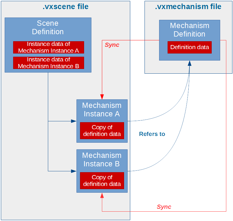
The Vortex Studio Editor allows you to create five types of content documents: Assembly, Gallery, Mechanism, Scene, and Control Interface. When a user creates a Mechanism (or any other content object), it creates a definition. When a user inserts that Mechanism into a Scene, it uses a special copy of that definition: an instance.
Other Definitions
Control Presets, Simulators, and Application Setups (i.e class ApplicationConfig) are also definitions, but they are not content files and work slightly differently. They are not covered in this section.
A definition consists of a main IObject (the parent) and some associated instances of IObject and IExtension (the children) saved into a file.
An instance is a copy of a definition which remembers the definition it came from. To put a definition object into another, it must be instantiated.
Since an instance remembers its definition, when that definition changes, the instance can receive the changes via the synchronization operation called sync.
The sync operation only brings the definition data to the instance. Definition data are the parameters of an object, as well as all the data of its children. The presence and order of the children are also definition data.
To complement the definition data that is common to all instances of the same object there are instance data. Instance data are the inputs/outputs distinct in each instance and are saved within the parent's definition.
There are 2 exceptions to this rule:
- The inputs and outputs values of a VHL interface extension, which can be a child of a Mechanism or a Scene, are instance data.
- The field
inputActivateof a Configuration is instance data. A configuration in a mechanism is usually activated at the scene level.
The editor handles definitions, instances, and sync properly without manual intervention. For example, to get the changes of the number of Parts into a scene, the Assembly instance of the Mechanism definition using it must be synced, then the Mechanism instances must be synced in the Scene definition. It is a manual process.
The Vortex Studio Editor only knows 7 types of Definitions: Assembly, Gallery, Mechanism, Scene, Control Interface, Equipment, and Exercise list, corresponding to the documents it can create. While the concept of definition can be generalized, the editor wouldn't know what to do with custom definitions.
A setup is also a definition, but they are not instantiated.
A simulator should not need to perform those operations, these are edition concepts.
Definitions and instances: example
Adding an Assembly to a Mechanism.
- The Mechanism is a definition (saved in a .vxmechanism file), an inserted Assembly in that Mechanism is an instance of an Assembly definition (that was saved in a .vxassembly file).
- Within the Mechanism document, the Assembly instance can be positioned using the inputLocalTransform field, the field is an input, that field is instance data belongs to the definition data of the assembly.
- If the Assembly is opened in its own document in the editor, it is the definition data is being edited, such as part mass and collision geometries.
- Any changes to the Assembly's parameters and children will be synchronized to the Assembly instance when going back to the Mechanism document in the editor. However, the position of the Assembly instance will remain the same.
- It works the same going up in the mechanism and scene.
Working with definitions and instances
Objects can be saved with the VxSim::VxObjectSerializer. Only definitions can be saved to a file. Object
The serializer can be used to load objects as well. Object loaded are thus definition. When a definition containing instances is loaded, all the definitions of the instance will be loaded as well.
All the instances are automatically synchronized after a load.
In a simulator, VxSim::VxSimulationFileManager can be used to load content. However, VxSim::VxSimulationFileManager::load(filename) returns an instance. The object returned is an instance and it is already added to the current VxApplication.
For content creation, it is recommended to use a VxSim::VxObjectSerializer, since you will need to work with definition.
Cloning
Cloning is an operation to copy an object. A clone is independent of its source.
Cloning a definition makes a definition. Cloning an instance makes an instance, linked to the same definition.
To clone, simple call function clone(), available in namespace VxSim by including file VxObjectHelpers.h.
Instantiate
Instantiating creates a copy of a definition, the resulting object is an instance but a link is kept to its definition. You cannot create an instance of an object that is not a definition. As mentioned before, instances cannot be saved on their own into a file, but instance data are saved with their parent definition.
To instantiate, simple call function instantiate(), available in namespace VxSim by including file VxObjectHelpers.h.
Bad Instances
There exists other IObject that are not meant to be definitions, something other than an Assembly, Gallery, Mechanism, Scene, and Control Interface e.g. a Terrain, a Human, or an Ocean. Attempting to instantiate such an object leads to undefined behavior and the file using the instance could be unusable by the Vortex applications.
Synchronization
The synchronize operation consists of updating an instance's definition data to match its definition while keeping the instance data. Once done, the children of the object are fully updated to match the children of the definition object.
To synchronize, simple call function sync(), available in namespace VxSim by including file VxObjectHelpers.h.
Creating Content in C++
All Vortex objects are extensions. Extensions are plugins and as such an object can be created using the VxSim::VxExtensionFactory with the proper VxSim::VxFactoryKey. However, the recommended way of using Vortex Object is by using VxSim::VxSmartInterface<T>::create() to create an extension of type T.
Note:
The following code snippets are not intended to produce a complete, runnable example when combined as-is.
Dynamics Objects
Most content objects are dynamics. These are your Mechanisms, Assemblies, Constraints, Attachment, Attachment Points, Parts, and Collision Geometries.
These Dynamics objects are represented by interfaces in the code (e.g. Part, Box), while the implementation is actually a dynamics extension provided by the dynamics plugin (VxDynamics.vxp).
A header file describes the interface that should be used by the developer (e.g. VxDynamics/Part.h).
The header file gives access to everything the user needs to make it work: the factory key and fields to each input, output, and parameter. Some utility functions are also provided.
An ICD header file describes the name of each input, outputs and parameters should a user needs to access them in a generic fashion from a VxExtension.
Dynamics objects Assembly and Mechanism can be loaded and saved to disk.
Moving Dynamics Objects well
Every dynamics object that can be moved implements the VxSim::IMobile interface. The position of a IMobile is set by the input inputLocalTransform and the actual position of an object is given by the output outputWorldTransform.
To move an object, rather than setting the value of the inputLocalTransform field is recommended to use function setLocalTransform().
Collision Geometries
The following code gives an example of using a box collision geometry extension.
Parts
The following code gives an example of creating a part:
Assemblies
The following code gives an example of creating an assembly:
Constraints
The following code gives an example of creating an hinge constraint with the minimal inputs:
Attachments
The following code gives an example of creating an attachment with two attachment points, each referencing a different part. The example attaches part together by adding an attachment to the assembly.
Attachments can be added to a mechanism or a scene to attach assemblies or mechanisms, respectively.
Mechanisms
The following code gives an example of creating a mechanism:
Other content extensions
Scenes
Scenes are where you put all your mechanisms for your simulation.
VHL Interface
VHL Interfaces are extensions that give direct access to its children's field by mapping it to a VHL field. VHL Interface can be added to a mechanism or a scene.
Adding inputs, outputs or parameters is available through the interface.
Connection Container
Connection containers are extensions that will contain connections between fields. Fields that can be connected must be children of the connection container's parent, typically a mechanism,
Adding connections is available through the interface.
Python Scripting Extension
Python scripting extensions are standard extensions to control an aspect of the simulation in code. There are handled by the dynamics module and are added to a mechanism or a scene.
The script file parameter refers to the .py file to execute. It is also possible to set the python code to execute as a string into the code parameter, but it is less convenient for edition.
The script extension can be edited to dynamically add inputs, outputs, and parameters that can be used by the python script.
The added fields can be referred to by the script using self.inputs.<field added>, self.outputs .<field added>, self.parameters .<field added>, where <field added> is the name of the field with invalid characters replaced by an underscore. The value is available from the value property of the python field.
Python extension does not have a dedicated interface, VxSmartInterface of IExtension should be used.
Configuration
Configuration are extensions used by mechanisms and scenes to configure them. By this, we mean that a configure is a set of modifications to the content that can be applied or not. The main goal is to make the mechanism or scene more reusable. Rather than having multiple copies of the object which just a small number of differences, configuration allows you to keep one base object and as many distinct configurations as you want.
Configurations are set when the application is in editing mode before the simulation is run. They cannot be changed in simulation mode.
Basics
- When added to an object (a mechanism or a scene), the
VxContent::Configurationcan references other extensions in the same object, allowing to modify inputs and parameters of referenced extensions or remove them from the content. - A configuration does not create extensions, the extensions must be in the object without configuration.
- An object can have multiples configurations.
- Configuration is only a set of modifications to be applied to one or many referenced extensions. The type of modification is called Actions.
- The actions are applied to the referenced extensions when activated.
- Multiple configurations can be activated at the same time, but a Configuration cannot be activated if there is a conflict between changes.
- Activation can only happen while the application is in editing mode.
Configuration Actions
A configuration can do one of the following actions, given by enum eConfigurationAction, on a given referenced extension:
Modify (
kModify) :When configuration is activated, selected inputs/parameters values are modified in the referenced extension; The referenced extension will be sent to the modules normally.
When configuration is not activated, all inputs/parameters values are untouched in the referenced extension; The referenced extension will be sent to the modules normally.
This is the default action.
Remove (
kRemoveOnActivation) :When configuration is activated, the referenced extension will not be sent to the modules.
When configuration is not activated, the referenced extension will be sent to the modules normally; All inputs/parameters values are untouched in the referenced extension.
Add (
kAddOnActivation):When configuration is activated, the referenced extension will be sent to the modules normally; Selected inputs/parameters values are modified in the referenced extension.
When configuration is not activated, the referenced extension will not be sent to the modules.
Configuration Conflicts
Two configurations will be in conflict if:
- They are modifying values in the same extensions.
- One configuration modifies values and the other wants to remove the extension.
- One configuration wants to add an extension, and the other wants to modify or remove the same extension.
How it works
The configuration extensions are handled by the Configuration Module. The module is part of a VxApplication and does not need to be added by the application setup.
The activation of a configuration is not instantaneous, it requires an update so that it can be treated by the Configuration Module and propagated properly across the network.
The field inputActivate is instance data, activating a configuration in a mechanism definition won't affect which configuration is activated in the scene. An activated configuration in the definition only affects which configurations will be activated when the instance is created.
A Configuration in a Scene can refer to a Configuration in a mechanism instance, allowing to use of the Configuration of a scene to configure a mechanism.
Activating or editing a configuration must be done in editing mode. Adding references should be done when the extension is not activated. In order to have a different set of inputs or parameters values for a reference extension, it must be added to a configuration (with action kModify or kAddOnActivation), then the configuration must be activated. When a user edits the values of a referenced extension, the changed values will only be in effect when the configuration is activated if the configuration is activated. The code sample below shows an example.
Using the Configuration API
The Configuration API offers several functions to ease the edition.
- Function
addReference()allows you to reference an extension in a configuration, with one of the following action:kModify,kRemoveOnActivationorkAddOnActivation- Function will return a ConfigurationErrors container. If it is not empty, it is possible to inspect each configuration error to find out the problem.
- Function
canAddReference()will help you figure out if you can add a reference to an extension in a configuration.
- Function
removeReference()allows you to remove a reference to an extension in a configuration. The returned object can be kept to revert the removed extension with all of its modifications. - To activate the Configuration, the field
inputActivateshould be set to true. It requires an update to be propagated.- If there is a conflict, configuration will not be activated but will stay in that state. If the conflict gets resolved, it will activate on its own.
- Use field
outputActivatedto determine activation success. - Use function
getRuntimeErrors()to find out a conflict in activation. - Function
canActivate()should be called before settinginputActivateto true, to know what will be the result of the activation. - Function
restoreReference()allows restoring a removed extension with its set of modifications. - Function
getReferencedExtensions()allows consulting the referenced extensions with their associated actions within a configuration.
Graphics Objects
The creation of graphics objects (including Terrain) in code is a complex subject out of the scope of this guide. Please use the Vortex Editor to manipulate Gallery and its sub-objects.
Content Creation in python
Content can be created in python as well, see Integrating Vortex Studio using Python 2 - Deprecated
Content Creation Tutorials
See the following C++ and python tutorials for example on content creation and manipulation.
Content Creation Tutorial (Python 3)
Content Parsing Tutorial (Python 3)
Content Creation Tutorial (Python 2)
Content Parsing Tutorial (Python 2)