Textures
When you select a texture, a 2D preview of the texture and its properties are shown in the Properties panel.
To add a texture to a Graphics Gallery
- Double-click Graphics > Texture in the Toolbox.
- In the resulting window, browse to the image you want to use as a texture.
- A dialog box will open asking whether you want to compress the texture. If you change your mind, you can undo this action via the Texture Tools options by right-clicking the texture in the Explorer panel .
Follow these steps to set the properties of a texture.
- From the Explorer panel, click on the texture to load the texture's Properties panel. If the texture is assigned to a graphics material, select the material in the Explorer to bring up its Properties panel, hover the mouse over the desired Texture field and click the Jump button.
- Set the following inputs:
- UV Offset: Adds an offset to the UV coordinates.
- UV Tiling: Specifies the number of times the texture repeats in the graphics model.
- UV Angle: Adds a rotation to the UV coordinate.
- UV Set: Determines which sets of UV coordinates to use in the graphics model. This value should not exceed the UV Set Count of the graphics geometry mesh in question. By default, a model has one UV set but more can be added by a graphics artist during the creation of a mesh, allowing you to add more detail to a model. See for Multi-texturing Using Multiple UVs for a deeper discussion of UV sets and their use.
- Checking Flip Green Channel is useful when importing common OpenGL normal maps. (This feature is only supported on normal maps.)
- Choose one of the values from the Filtering drop-down list to define how to interpolate between texels when the texture coordinate provided lies in between two or more texels. Supported values are:
- Point
- Linear
- Bilinear
- Trilinear
- Set the Anisotropy parameter. The supported range depends on the video card (typically [1.0 - 16.0]).
NoteSetting a value beyond 1.0 will force Anisotropic Filtering.
- Set the WrapModeU and WrapModeV texture wrap (addressing) modes to define what to do when the texture coordinate provided lies outside of the texture image. Supported values are:
- Repeat
- Clamp
Multi-texturing Using Multiple UVs
One method of creating realistic-looking graphics models is through multi-texturing. To apply textures and materials, you need to start from a 3D model. Creating a 3D model requires a 3D modeling software (either commercial or open source). There are a few rules to remember when applying texture to a 3D model. Some of these rules are reviewed below but we advise that the Graphics Gallery user have prior 3D modeling and texture training, as basic 3D concepts are not covered here.
There are two common methods of creating textures:
- Create a very detailed 3D model that closely resembles the real-life object, and a second model only modeling the general forms (referred to as high resolution and mid/low resolution, respectively). The textures generated from the high resolution model are used on the low model, resulting in a high detail model with a low triangle cost.
- Create a model that approaches the shape of the real-world object, then paint in the details in a software designed for this purpose.
The second method is used for this topic.
Background
UV represents the coordinates in 2D of the unfolded surface of a 3D model, allowing the application of a 2D texture on a 3D object in a 3D world. U and V are used to avoid confusion with (x, y, z) used for space coordinates.
By default, most 3D modeling software will create one UV set for a 3D model; adding another can allow emphasis to a particular 3D component, which would not be possible with a single large UV. Adding more UV sets must be done in the 3D modeling software before being imported into Vortex® Studio Editor.
A 3D model can be broken down into as many UV sets as desired, though 2020a supports a maximum of four, which is usually more than sufficient to add an enormous amount of details.
Note Textures must be kept in mind when modeling, and it's important to plan the locations of the seams where the edges of the textures will meet ahead of time. Sometimes, it is necessary to force an additional texture seam by creating a physical edge, line or seam in the right place on the model. Since textures are projected on the model, it's critical to correctly manage the triangles in face mode with the polygon edit tools in the 3D modeling software, so the textures will follow the surfaces correctly and not suffer from deformations and stretching. Note that multiple UV sets are a tool for multi-texturing but are not required it. It's possible to layer multiple textures on a single UV set. However, additional UV sets afford more flexibility to the user in how to apply textures to a model.
Buoy Example
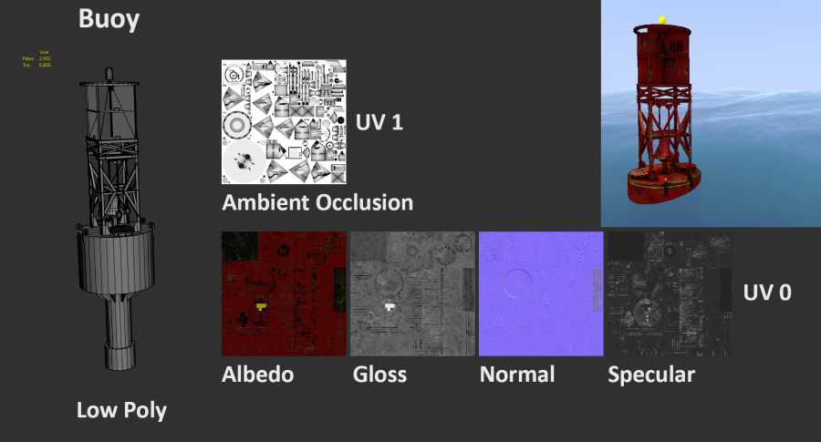
In the example below, we demonstrate applying multiple UV sets and textures to a maritime buoy. In this case, a second UV set (identified as UV1) represents the ambient occlusion, while the main UV set (identified as UV0) represents the objects composing the buoy split in another way, which provides different details.
The buoy was intended to be seen from far away, so the textures have been created with this in mind. It's important to keep the volume that defines the buoy, so the normal map has a large resolution (4k). It could also have been attached to another UV set, in order to add even more details without affecting the size of the rest of the textures. This is at the user's discretion, and depends on the time and effort one is willing to put into the model.
|
| A low polygon buoy, the textures that make up its UV sets, and a preview of the buoy in a scene (emissive, not shown) |
|---|
|
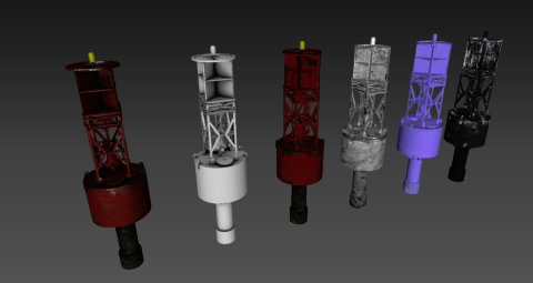
|
| The buoy with all the textures applied (on the left of each image), followed by each texture individually (ambient occlusion, albedo, gloss, normal, and specular), from different angles (emissive, not shown) | |
|---|---|
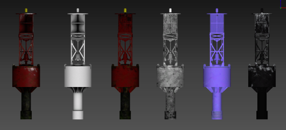
The different texture layers are shown in the images above: ambient occlusion, albedo (for colors), gloss (for shininess), normal (for surface details), and specular (for reflectivity). The emissive layer is not shown but would be used for texturing the warning light on top in the above example.
Notice that the model has a low polygon count, constructed with just the necessary shapes. Since there are no specific details to highlight, all textures are applied using UV0, except for the ambient occlusion. The occlusion uses UV1 since it has a different surface unfolding, based on the connecting surfaces, resulting in a better-looking output.
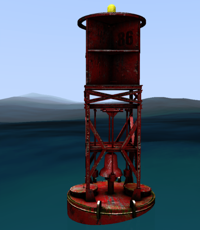
You can see the end result in the image below, after all textures and UV sets are combined. The contour is a texture that distorts the volume (normal map) and the suggestion of volume is created by the ambient occlusion on a different UV set, UV1.
|
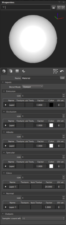
|
| The buoy in the scene, textures applied | The Materials Properties panel |
|---|
Multi-texturing
As its name implies, multi-texturing allows two or more textures to lay one on the other, having a compositional interaction.
Multi-texturing requires a homothetic unfolding on a UV set. This notion is important because it will allow the user to add detail elements (like dirt) without worrying about unfolding it in a UV texture space. Unique textures can be used in conjunction with seamless textures (textures that can be multiplied, tiled, and offset), with the end result being models with rich details, even with relatively low resolution textures.
Suggested UV Set Conventions
We suggest separating your UV sets in the following way:
- UV0: Albedo/base colors
- UV1: Ambient occlusion
- UV2: Normal map
- UV3: Other details
Note UV0 can be used for all texture types; using additional UV sets allows detailing specific locations on the model, or gives better control for how the textures are mapped to the surfaces.For example, you can add zones of high resolution text without having to include the entire albedo, normal, specular, etc., textures of the model in high resolution. Ambient occlusion, used to add volume and definition to the object, can be set into its own UV to allow the shadows to be placed more accurately. Surface effects, such as dirt, can be added separately on their own UV set with dedicated textures, or via adding a repeat texture to an existing UV.
Suggested UV Nomenclature
- UV0: Used for the base channels of emissive, albedo, specular, and gloss. Additional UVs can be superimposed to cover seams and add more details (e.g., via masks).
- UV1: Used for ambient occlusion. This is usually set on its own UV because overlapping seams with the base channels must be avoided to keep a clean overlay. A custom UV must therefore be created according to the represented objects, with seams being placed at the connection between two surfaces and nowhere else. Note that this will usually result in a fairly complex UV unfolding.
A seam will be a cut in the surface, therefore a black line will occur due to the two pixel spacing around the form, which will be enough to merge to black. This line should be avoided at all costs on surfaces, and instead be placed at the connection between two physical components, where it will justify the existence of a shadow in the corner (and thus be hidden by it). To do this, it will be necessary to break the UV and force the proportions; this cannot be automated, so it must be done by hand, based on the artist's experience. It's probable that it will be necessary to stretch the texture projection to have good results (note that this advice is specific to ambient occlusion). The resulting texture must be neutral (without volume), or the projection will take it into account and create artifacts. - UV2: Used for normal maps. One can maximize the space of the normal maps by placing them in their own UV set (in this case, UV2). In 2020a, normal maps can be superimposed, so that if UVs repeat, we can superimpose them to save space in the UV environment.
A normal map brings an additional level of detail and a sense of volume. However, it must be laid on a 3D object that already has volume, not just a flat surface. It imparts an added suggestion of volume that fools the eye into adding details not present on the polygon model.
There is a technique to maximize the use of normal maps without overlapping them physically. Mirror the UVs when you mirror the vertex positions, so that the main UV map contains only the right information, the repetition of the textures generating the correct layering.
Creating Effects
UV sets have other uses in addition to those above, for example to help break repetition in surface textures, or to create complex surfaces.
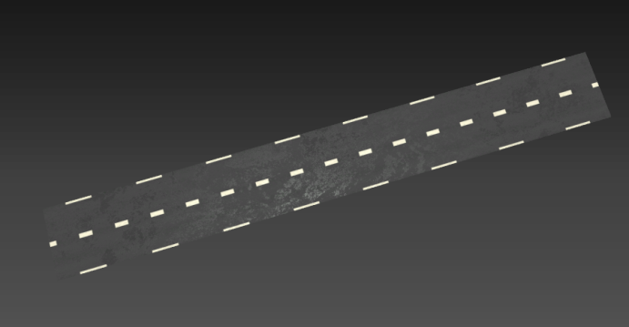
Example 1: Road
In this example, the texture of the road is repeated in UV0 and UV1. In UV1, however, the road texture and a mask are assigned to the Gloss channel. All merge together to create a "wet" effect.
|
| Wet road effect created with two UV sets |
|---|
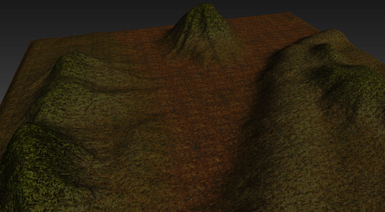
Example 2: Landscape
In this example, the multi-texturing and tiling of the ground is obvious from a bird's eye view.
|
| Bird's eye view of a landscape using multi-texturing and tiling |
|---|
But from a ground-level point of view (below), the multi-texturing is used to hide the repetition. It's important to know how the final model will be viewed.
|
| Ground-level POV of landscape; multi-texturing hides the repetition of tiling |
|---|
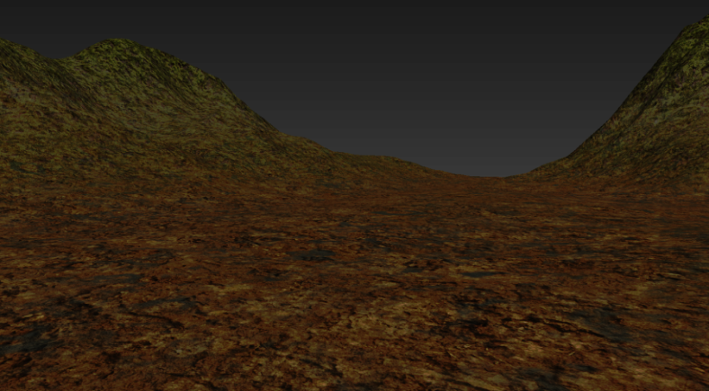
This scene was created with the ground-level POV in mind, because from that perspective, it hides undesirable effects like tiling (as seen in the above image). If the scene were intended to be viewed from higher above, we would have worked the textures differently to avoid this tiling effect.