Graphics Extensions
- DEVOPS
 These are the following categories of effects that you can apply in Vortex®:
- Particle effects: Used to simulate a large number of very small objects, such as a cloud of dust.
- Image effects: Used to affect the look of the simulation, not the physics. Note that since they involve calculations, image effects do impact performance.
Adding an effect
- Select Effects in the Toolbox.
- Click the desired effect and drag it into the 3D View.
- Edit the name of the effect.
- If adding a particle effect, attach and/or place it using the transform controls.
Color Grading
The Color Grading extension allows you to alter and enhance the colors of your scene. It can only be added at the Scene level.
Color Grading modifies the colors represented on the screen by applying a tone mapping function (i.e., bringing high dynamic range back to low dynamic range for the monitor to render the pixels) and a color correction transformation.
In the Properties panel, configure the following fields:
- Color LUT: Color correction is implemented through a 256x16 image/color lookup table (LUT). After tone mapping is applied (see next bullet point), the LDR color from the scene is replaced by its related color from the LUT.
To add multiple presets LUTs (including sepia and warm LUTs), right-click the Color Grading extension in the Explorer panel and select Insert Color Grading LUTs. Otherwise, another way to use this feature is to take a screenshot of a rendered image and modify it through graphics editing software, as well as modifying a neutral LUT in the same way, in order to create a mapping between the original colors and the modified ones. Add the LUT to your scene as a texture then link it to this field.
Consider the following neutral LUT to use when applying filters:
The following are some examples of modified LUTs:


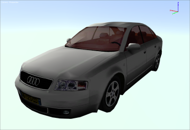
Thee - Tone Mapping: Used to map pixel colors, which are in high dynamic range (HDR) in Vortex, to the low dynamic range (LDR) used by monitors. HDR rendering allows Vortex to have a bigger light to dark ratio, making it possible to have strong lights and darker zones in the same scene.
This extension defaults to a custom function, but the following tone mapping presets are available, each with their own adjustable settings:- Engine (default)
- Hable
- Linear
- Dawson
- Reinhard
- Exposure: Value used to control the scene's color exposure, measured in time (seconds).
- Exposure Bias: Value meant to overexpose or underexpose the colors, to better simulate the exposure effect of the human eye.
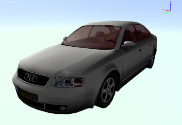
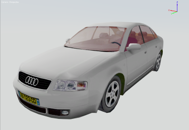
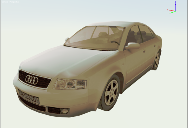
Example
Consider the following images:
|
|
|
|
Decal
Placing a decal allows you to add a material on top of an object in your scene, mechanism or Graphics Gallery. After adding a decal, a box appears with an arrow inside. The decal box acts like a projector. Place the box over the object upon which you want the decal to appear, and orient the arrow to point in the desired direction using the rotation tools. The decal will be projected on a surface area inside of the decal box.
In the Properties panel, configure the following fields:
- Local Transform: Use these fields to position, resize and orient the decal. You can also use the Transform toolbar or the manipulators in the 3D View.
- Visible: Select this box to make the decal appear.
- Receive Shadow: If selected, the decal will receive shadows cast by other objects.
- Graphics Material: Click the details button in this field to select a graphics material from the Explorer panel to use as the decal.
- Terrain Decal: Select this box to ensure the decal is only rendered on the terrain. In this way, the decal ignores non-terrain geometry, which is useful to avoid stamping terrain details on vehicles or other objects.
Override Normals: Select this box to make the decal override the normals beneath it, rather than blend with it. This is useful to draw details like puddles or access hole covers.
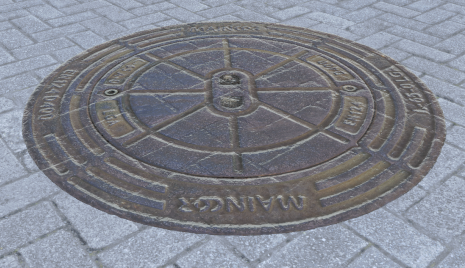
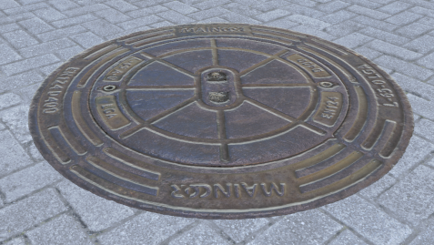
Access Hole Cover — Default Normals Access Hole Cover — Override Normals Directional Projection: When selected, the decal will only stamp on aligned surfaces. This is useful to avoid leaking decals on the sides of meshes, or to render snow accumulation, for example.
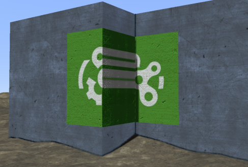
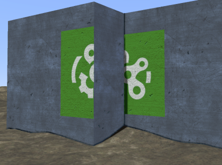
Default Behavior Directional Projection 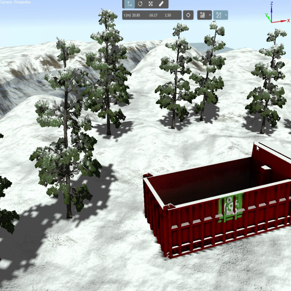
Snow Accumulation
Selecting this box reveals these parameters:- Maximum Surface Angle: Determines the maximum deviation (in degrees) of the surface upon which the decal is projected.
- Fade Length: Sets the arc length (in degrees) of the decal fade past the maximum surface angle
Desaturate
Adding the Desaturate image effect removes color from the scene. In the Camera Name field, enter the name of a viewport in order to display it in greyscale.
Anti-aliasing
Anti-aliasing is a computer graphics technique used to remove jagged and pixelated edges from images. Vortex Studio supports the following anti-aliasing techniques.
- Fast Approximate Anti-aliasing (FXAA): A post-processing method that does not require large amounts of computing power, trading quality for speed. It smooths jagged edges based on how they appear on-screen, rather than analyzing the 3D model itself. Thus, FXAA will smooth not only edges between triangles, but also edges inside alpha-blended textures or resulting from pixel shader effect. However, textures may not appear as sharp if they are included in the edge detection.
- Multisample Anti-aliasing (MSAA): A special case of supersampling, performed by the graphics card. This technique smooths jagged edges by analyzing the pixels of each frame and performing a smoothing/blending process. The 2x, 4x, 8x and 16x values indicate how many samples are used for each pixel to compute the average that is ultimately displayed. The higher the number, the better the quality of the anti-aliasing at the expense of speed. MSAA is good at smoothing edges and lines, but it isn't as effective at smoothing textures or color detail. Because of the way alpha testing works, the edges of transparent objects (or edges within textures) may be missed, though the quality will be no worse than without anti-aliasing. MSAA is multiple times more calculation-intensive than FXAA or SMAA, so be ready to reduce the sampling if framerate suffers.
- Subpixel Morphological Anti-aliasing (SMAA): A post-processing technique, similar to but slower than FXAA while producing better results. SMAA is better than FXAA at handling sharp geometric features and diagonal shapes by exploiting local contrast features, along with more precise distance searches. However, it requires more system resources.
- SMAA S2x: A hybrid method that first runs the MSAA 4x antialiasing, then follows with SMAA post-processing afterward, aiming to combine both quality and speed. Start here if quality is an important factor for your needs but it is slower than all other options except MSAA 8x and 16x.
The anti-aliasing extensions are not added in the Editor via the Toolbox like other extensions but rather through the Application and Add-ons Options.
High Dynamic Range (HDR)
The HDR effect allows you to increase and fine-tune the brightness and contrast in your scene by specifying values for the following:
- Target Luminance: Average luma value of the image, after the post-effect is applied.
- Luminance Scale: Maximum distance for the luma values compared to the average.
Luma represents the brightness in the black and white portion of an image (separate from chrominance, which conveys color information).
In the Camera Name field, enter the name of a camera in order to apply HDR to it.
Impact Event Particles
The Impact Event Particles extension creates particles only in the case of impact with another object.
In the Properties panel, configure the following fields:
- Particle Lifetime (in seconds): Determines how long the particle will exist after its creation.
- Particle Size Change: Determines the range of possible sizes of the particles, in meters.
- Particle Alpha Change: Determines the range of possible transparency of the particles.
- Particle Alpha Fade Interval: Determines how many seconds will pass between the particles fading in and out.
- Particle Color Start: Determines the starting color of the particles. The four color fields represent red, green, blue and transparency.
- Particle Color End: Determines the ending color of the particles. The four color fields represent red, green, blue and transparency.
- Particle Color Change: Determines the variance in color for the particles within the start and end colors selected above.
- Particle Angle Start Range: Determines the range of angles at which the particles can be oriented at their creation.
- Emission Rate: Determines how many particles are emitted (in hertz).
- Spray Cone Theta Range: Determines the range of angles from the +X-axis and the spray cone can take (in degrees).
- Spray Cone Phi Range: Determines the range of angles from the +Z-axis and the spray cone can take (in degrees).
- Spray Linear Speed Range: Determines the range of linear speeds the particles can travel (in meters per second).
- Spray Angular Speed Range: Determines the range of angular speeds the particles can rotate (in degrees per second).
- Gravity Acceleration: Changes the effect of gravity on the particles (in meters per second squared).
- Material File: Selects the material used for the particles.
Noise
The Noise effect introduces a configurable level of graininess to the view, for example when simulating a low-definition security camera. The Intensity field specifies the level of noise applied to the viewport specified in the Camera Name field.
Particle Culling Box
A particle culling box is a conceptual shape used to forcibly remove particles. For example, to simulate airborne dust being reabsorbed into the ground, a culling box can be set up at ground level to eliminate dust particle upon contact.
Upon creation, the box is a cube where its five sides (the top of the cube is open) destroy particles from the scene when contact is made with them. You can change the box's size and placement by using the transform controls.
Particle Spray
A Particle Spray extension allows you to create a spot from which particles emanate.
In the Properties panel, configure the following fields:
- Particle Lifetime: Determines how long the particle will exist after its creation (in seconds).
- Particle Size Range: Determines the range of possible sizes of the particles, in meters.
- Particle Alpha Range: Determines the range of possible transparency of the particles.
- Particle Alpha Fade Interval: Determines how many seconds will pass before the particles fade away.
- Particle Color Start: Determines the starting color of the particles. The four color fields represent red, green, blue and transparency.
- Particle Color End: Determines the ending color of the particles. The four color fields represent red, green, blue and transparency.
- Particle Color Change: Determines the variance in color for the particles within the start and end colors selected above.
- Particle Angle Start Range: Determines the range of angles at which the particles can be oriented at their creation.
- Emission Rate: Determines how many particles are emitted (in hertz).
- Emission Enabled: Determines how many particles are emitted based on an outside factor (e.g., the degree at which a gas pedal is pushed in a car). The higher the value, the more particles are emitted.
- Emission Box Minimum: Determines the minimum dimensions of the box from which particles emit.
- Emission Box Maximum: Determines the maximum dimensions of the box from which particles emit.
- Spray Cone Theta Range: Determines the range of angles from the +X-axis and the spray cone can take (in °).
- Spray Cone Phi Range: Determines the range of angles from the positive z-axis and the spray cone can take (in °).
- Spray Linear Speed Range: Determines the range of linear speeds the particles can travel (in m/s).
- Spray Angular Speed Range: Determines the range of angular speeds the particles can rotate (in °/s).
- Gravity Acceleration: Changes the effect of gravity on the particles (in m/s2).
- Material File: Selects the material used for the particles.
Label
Adding a Label allows you to place a string of text into your scene or mechanism.
In the Properties panel, configure the following fields:
- Visible: Toggles whether the label is visible.
- Local Transform: Use these fields to position, resize and orient the decal.
- Text: Enter the text you want to display here.
- Text Orientation: Allows you to select in which direction the text is written. From the drop-down menu, select Horizontal or Vertical.
- Text Size: Specifies the size of the text.
- Text Color: Specifies the color of the text. The four color fields represent red, green, blue and transparency.
- Font Height: Enter the height of the displayed font (in meters).
- Font File: Click the details button to select a TrueType font file (.ttf extension) to use for the displayed text.
- Outline: Select this box to put a dark outline around the letters of the text.
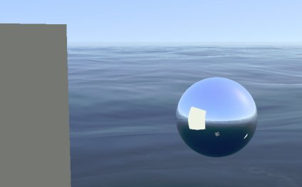
Light Probe
The Light Probe extension captures the incoming lighting at a specific location in the world and uses that data to generate the reflection of an object using a PBR material. It is available at both the scene and mechanism levels.
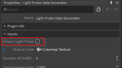
It is important to note that Vortex Studio Editor only supports one distant light probe at a time. If you add a light probe, make sure to disable the distant light probe associated to any SkyDome or SkyBox extensions you may be using. To do this, expand the SkyDome or SkyBox in the Explorer panel, then click on its Light Probe Generator sub-heading. In its Properties panel, deselect Distant Light Probe.
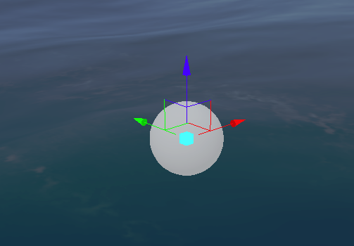
Once the light probe is added, place it in the middle of the scene, preferably in the center of the object with the PBR material.
Next, remove everything from the scene whose reflection you do not want captured by the light probe (e.g., the object using the PBR material, other accessories). Use the Trigger Capture input to recompute the light information.
Next, replace the objects you previously may have removed.
|
|
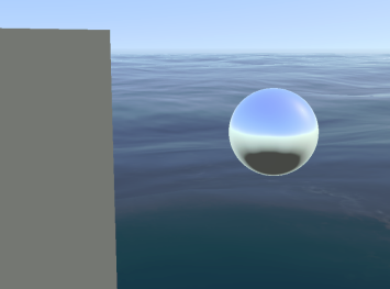
| Reflection without light probe | Reflection with light probe |
|---|
In the Properties panel, configure the following fields:
- Local Transform: Use these fields to position the light probe. You can also use the Transform toolbar or the manipulators in the 3D View.
- Trigger Capture: Select this box to recapture the light probe's data. This information can also be recomputed by moving the light probe. The resulting texture data is named "Cubemap Texture", as seen in the Texture Cube output. It is also available in the Explorer panel by expanding the Light Probe.
- Cubemap Face Size: Sets the resolution (in pixels) of a cubemap side (values can range from 1 to 4096).
If you need to edit any PBR-related values, expand the Light Probe in the Explorer panel and select Light Probe Data Generator. See Physically Based Rendering (PBR) Materials for more information about the inputs you will find in its Properties panel. The textures found by expanding the Light Probe in the Explorer panel are for illustrative purposes only and need not be edited.
Graphics Material
The Material extension allows you to add a graphics material to your scene or mechanism. See Graphics Materials for detailed information.
Text Texture Generator
The Text Texture Generator allows you to add custom text to a mechanism by selecting a node in the Textured Node field.
In the Properties panel, configure the following fields:
- Text: Specify the text you want to appear.
- Text Size: Specifies the size of the text.
- Text Color: Specifies the color of the text. The four color fields represent red, green, blue and transparency.
- Textured Node: Selects the node upon which to overlay the text.
- Resolution Width: Specifies the number of pixels used to represent the width of the text.
- Resolution Height: Specifies the number of pixels used to represent the height of the text.
Texture
Double-click Texture to insert a previously-created texture into your scene or mechanism. Once inserted, right-click the texture in the Explorer panel and select Texture Tools to export, re-import, compress or decompress the texture.
If you import a texture already formatted as a texture cube, Vortex Studio will recognize it as such and handle the texture cube correctly.
Texture Cube
Double-click Texture Cube to create a six-faced texture box. A window will open where you can select a different texture for each side of the box.
A texture cube is used in conjunction with a SkyBox.
Vehicle Trace
Double-click Vehicle Trace (or drag and drop it into the 3D View) to add an extension to your scene or mechanism so your vehicle using threaded tracks or wheels can leave behind markings as it drives across a Terrain. These trails are only left on a terrain geometry.

Note In order for a trace to leave a stamp, you must first connect the trace's parent transform to the vehicle's world transform, using a connection container.
When you add a Vehicle Trace to a scene or mechanism, a red box appears to represent the area where the trace texture will be projected. Anywhere terrain intersects the box, the stamped trace texture will be visible.
In the Properties panel, configure the following fields:
- Visible: Toggles whether the trace is visible.
- Receive Shadow: If selected, the trace will receive shadows cast by other objects.
- Local Transform: Use these fields to position, resize and orient the vehicle trace area.
- Rotating Wheel: Select this box if this vehicle trace is attached to a rotating wheel (as opposed to a track, for example). It is assumed the wheel rotates about the local Y-axis.
Textures (Albedo, Normal, Specular): Textures from all vehicle traces are collected when the simulation starts, and they create a texture atlas. The atlas supports textures (without masks) for albedo, normal and specular, specified in these fields by clicking the Browse button in each field and selecting the required texture from the Explorer panel.
The maximum atlas texture size for a channel is 4096 pixels. A padding of 8 pixels is applied around each vehicle trace texture a before it is baked into the final atlas texture. The atlas does not support compressed images.- Dimensions: Specifies the vehicle trace area (in meters). Resize this box to encapsulate the part of a wheel or track that makes contact with the ground. Make sure this box covers the contact point as well as descending a little through the terrain, to ensure the traces will be visible even if a small amount of soil is added or removed.
- Distance threshold: Specifies the distance (in meters) the extension needs to move before a new trace is stamped. For performance reasons, keep this value as high as possible while maintaining acceptable visual results.