Terrain
- DEVOPS
 A terrain is available only at the scene level and represents the land relief (physical geography) on which rigid bodies can interact.
A terrain consists of a set of tiles generated from a Graphics Gallery file, which you import in the Scene Editor, only one terrain per scene is allowed.
The Editor uses a basic parametrization in order to subdivide the terrain's polygons into tiles. When you first import terrain file, and any time you need to edit the terrain object, you can change this default parametrization in these ways:
- By default the UV plane of the grid is mapped to the local XY plane of the terrain, which means that the local Z axis corresponds to the up axis in the simulation. You can change one or both of the UV axes to use any of the XYZ axes.
- You can change the default number of cells (which is
100) along the terrain's U and V coordinates. - By default only one level of hierarchical subdivision is performed, but you can increase this by specifying a maximal number of subdivisions.
- If you enable hierarchical subdivision, you can also specify how many sub-cells to create, as well as a minimum number of triangles per cell to prevent further subdivision.
In addition, you can build a list of mapping rules that allow you to specify which materials are mapped to which textures, and you can also turn off shadow casting for the terrain to boost the resolution of your shadow maps.
Once set up, a terrain can be modified in terms of the parametrization, the material mapping, the shadow casting, and you can even specify an entirely new file to use.
Adding a Terrain to the Scene
You can add a terrain to a scene that Vortex® will build from the Graphics Gallery (*.vxgraphicgallery) file that you specify.
- If you are not already in the Scene editor, either open an existing scene or create a new one.
- To add a terrain, select Environment in the Toolbox, then double-click Terrain From File.... A dialog panel appears.
- Click the Browse
 button to the right of the Terrain File text box under the Source section and double-click the file you want to use from the file browser.
The file name you specified appears in the Terrain File text box. - To specify how you want to map materials in the terrain, you can set up a number of rules using regular expressions that will match either nodes or textures to materials.
For more information, see Mapping Materials on the Terrain. - If you want to change the default parametrization that Vortex uses to generate the terrain from the file, you can follow the instructions under Tweaking the Terrain Parameters.
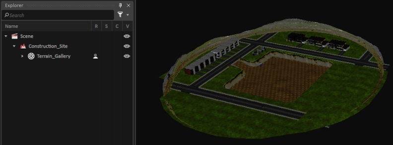
- When you are satisfied with the parameter settings for generating the terrain from file, click Ok. The Editor generates a new terrain from the parameters you specified (which may take a while, depending on the complexity of the file and the parametrization). When completed, the new terrain appears in the 3D View and a new Terrain object appears under the scene in the Explorer Panel.
Note You can return to modify the terrain specification at any time by following the instructions under Editing an Existing Terrain.
Editing an Existing Terrain
You can change how Vortex® generates your terrain by editing the same parameters you set up when you created the terrain in the first place.
- In the scene file that contains the terrain you want to edit, locate the terrain object in the Explorer panel.
- Right-click the terrain object and click Edit from the context menu. The 2812905045 will activate.
- Now you can make any of the following changes:
- Change the file from which Vortex will build the terrain by changing the value in the Terrain File text box.
- Change how the materials map onto the terrain (see Mapping Materials on the Terrain).
- Change the default parametrization that Vortex uses to generate the terrain from the 3D mesh file (see Tweaking the Terrain Parametrization).
- When you complete the modifications to the parameter settings for generating the terrain from file, click Ok.
The Editor regenerates the terrain from the parameters (which may take a while, depending on the complexity of the mesh and the parametrization). When completed, the newly regenerated terrain appears in the 3D View.
Mapping Materials on the Terrain
Most terrains contain several different objects or areas that need discrete materials to be applied, such as buildings, roads, bodies of water or ice, etc.
In order to define specific materials for each area of your terrain, you need to build a set of rules to tell Vortex® how to assign these materials.
You build each rule by matching the name of the node(s) or texture(s) where you want to assign the material with the name of the material to assign. You can use regular expressions to identify a group of nodes or textures, so for example, you could assign a name to every texture that appears on the side of a building with a designated keyword (Siding001, Siding002, Siding003, etc.) which can then be used in your rule (for example, Siding00.? or Siding.*, etc.).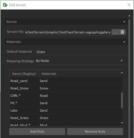
The material names you use must correspond to the materials table you are using for the scene. For more information about materials tables and how to use them, see Contact Materials.
Note The procedures in this section assume you are in the middle of creating or editing a terrain specification. If that is not the case, follow the instructions for either creating or editing a terrain before proceeding.
Setting the Default Material
Typically most materials tables contain a default material definition (usually also named default), and the Editor uses this material throughout the terrain unless you specify a different material to use.
If you have a terrain which is mostly sand (for example, a desert), you can set sand as the default material by typing the name into the Default Material text box:![]()
Warning If you specify material mapping rules to match node(s) or texture(s) to the specific materials, anything on the terrain that does not match these rules will use the default texture defined on the materials table you are using (not the material you specified in the Default Material text box).
Mapping from Textures
By default, Vortex® assumes that the rules defined for mapping materials on a terrain apply to the graphics nodes in the 3D mesh file.
However, you can change this to use textures instead by selecting By Texture from the Mapping Strategy drop-down box under the Materials section.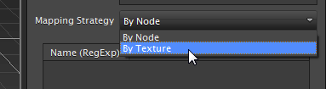
Building Rules
When you have a terrain with more than one texture requiring specialized materials, you can build a set of mapping rules that will match each specialized area to a material by naming the node(s) or texture(s) using a regular expression.
For example, if you have a terrain with several patches of ice, and the textures associated with these areas all use Ice in their names (Barn_Ice, Ice_Pond, Road_Ice_001, Road_Ice_002, etc.), you can capture these discrete areas using .*Ice.* as a regular expression.
Rule Ordering
The order of how the rules appear in the list is important: the first rule that appears takes precedence over subsequent rules.
For example, given this set of textures: Road_Asphalt_Wet, Road_Asphalt, Road_Gravel, Road_Sand, Road_Sidewalk, Road_Snow, Road_Grass, and a set of rules ordered as below, everything is assigned mat23 while mat09 and mat14 are never assigned anywhere because what appears in the list first matches everything:
Road.* => mat23
Road_Asphalt_Wet => mat14
Road_Gravel => mat09
But in the following set where the rules are ordered opposite, Road_Gravel is assigned mat09, Road_Asphalt_Wet is assigned mat14, and everything else is assigned mat23 because the specific rules for Road_Gravel and Road_Asphalt_Wet are allowed to make their matches before the general rule matches everything:
Road_Gravel => mat09
Road_Asphalt_Wet => mat14
Road.* => mat23
If you want to change the order of rules in the rule list, you must remove the earlier rule and re-add it to the list so that it appears after the other rules (see Adding and Removing Rules).
Adding and Removing Rules
To define a rule for mapping materials to textures or nodes, follow this procedure.
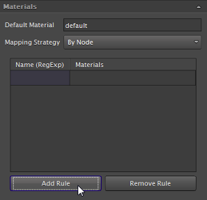
From the Materials section, click the Add Rule button.
A blank row appears in the list.
Double-click in the cell under the Name (RegExp) column and type the regular expression that describes the node or texture and press Enter. For example,
Road.*or.*_Texture00.?, etc.Double-click in the cell under the Materials column and type the name of the material and press Enter. For example,
ClayorSand, etc. The new rule appears in the list.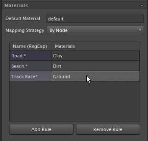
To delete a rule from the list, click anywhere on the rule and then click the Remove Rule button.
Repeat these steps for each rule you want to add to the list.
Tweaking the Terrain Parameters
While a terrain comes with default terrain parameters (or, UV Grid Parameters), you may need to modify it in order to achieve a good balance between cell-object and triangle-object bounding box overlaps. The editor provides a tuning tool, called the UV Grid Visualizer, which assists you in achieving this goal.
In order to optimize the terrain parameters, consider the following factors:
- The overall size of the triangle mesh
- The triangle density distribution in the mesh (large mesh regions represented by few, large triangles or many, small triangles)
- The size distribution of all objects which collide with the triangle mesh throughout the entire simulation (if there are very big objects and very small objects, hierarchical subdivision might be a good strategy)
For example, if you specify no subdivision at all (which is the default), the tiling strategy is to loop through all triangles in the mesh for each object and check whether the triangle is overlapping the object's bounding box. All overlapping triangles are then marked are candidates. In this scenario, the most time is spent on triangle/object bounding box overlaps, so this is one of the worst possible parametrizations.
The other extreme is having too many subdivisions (potentially including hierarchical subdivision levels). In this case, each triangle would lie in its own UV grid cell (or bucket). All the cells which overlap with the object's bounding box have to be found by making lookups in the grid and performing cell/object bounding box overlap tests. In this scenario, the greatest amount of time is spent on cell/object bounding box overlaps.
These changes can be entered in the UVGrid Parameters section of the terrain property when you are either creating or editing it: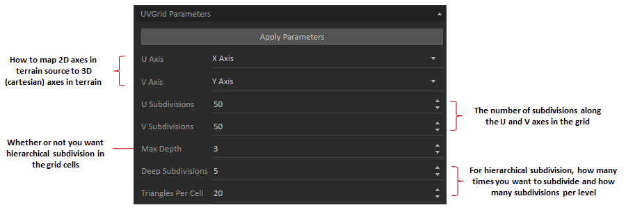
The Apply Parameters button allows you to directly change the terrain parametrization. You can see the results of these changes to the UV grid by using the color-coded UV Grid Visualizer.
If there are objects in the terrain mesh which extend high along the grid's up axis (for example, a skyscraper with its height extending along the local Z of the terrain), then hierarchical subdivision is very important.
When the grid is created, for each first-level UV grid cell, the hierarchical subdivision algorithm automatically detects the direction of largest extend (U cross V = grid up axis for a skyscraper) and then subdivides along this axis.
When, for example, a vehicle then approaches the skyscraper and it enters the first-level cell in which the skyscraper lies, the grid will be able to determine due to the hierarchical subdivision that only the lowest second-level cell in this cell is of interest. The vehicle can only collide with the base of the skyscraper. So all the other triangles are not considered as candidates for overlap with the vehicle, which is the desired behavior.
Finding good terrain parameters with the UV Grid Visualizer
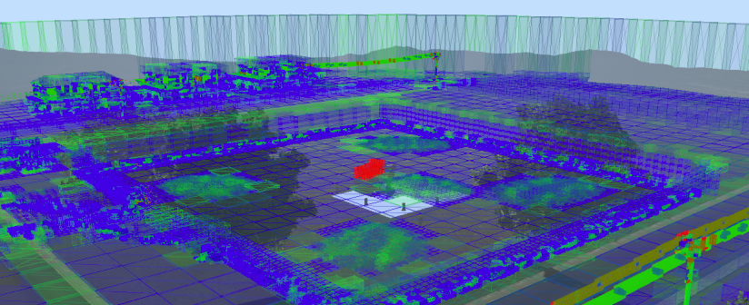
In order to assist you in finding good UV Grid parameters, the UV Grid Visualizer uses a color coded display providing an indication of the quality of the chosen parameter values (see image above).
The UV Grid Visualizer automatically activates when you are Editing an Existing Terrain in a scene or mechanism. However you can also add it via the Toolbox by selecting Environment > UV Grid Visualizer. By changing the UV Grid parameters and pressing Apply Parameters, you can immediately see the results in the display.
Background information
While editing terrain parameters, clicking Apply Parameters results in an immediate update of the underlying terrain collision grid (the UV grid). The effect on the UV grid will then be reflected directly in the visualization on screen.
The UV grid is a spatial acceleration data structure that speeds up the intersection checks between the terrain triangles and colliding objects, e.g., the wheels of your vehicle. It achieves this by sorting the terrain triangles into rectangular grid cells created via subdivisions along the local U- and V- axes of the terrain's UV plane. The local axes of this plane can be chosen in the UV Grid parameters.
When testing for collision between the terrain and an object on the terrain, only the terrain triangles in the cells of the UV grid nearest to the object need to be checked. Keeping these collision triangles to a minimum maximizes performance. Bad UV Grid parameters can lead to excessive numbers of triangles in the UV Grid cells, and thus to bad collision performance: this is to be avoided. The UV Grid Visualizer provides assistance in finding good UV Grid parameters via the color coding of the created cells.
Color Coding
The translucent boxes in the UV Grid Visualizer show the cells that were created by the subdivision of the UV grid, and their color is related to the number of triangles sorted into these cells.
The colorization of the grid cells indicates whether the number of triangle in the cells are good (relatively few) or bad (relatively high), based upon the Triangles Per Cell UV Grid parameter.
- Red: There are too many triangles relative to the targeted triangle count.
- Green: The number of triangles is very close to the desired triangle count. Note that the default for Triangles Per Cell is reasonable in most cases and usually does not need to be changed.
- Blue: There are fewer triangles than the targeted triangle count.
The UV Grid parameters should be chosen such that red cells are avoided as much as possible and the number of green cells is maximized. Blue cells are not necessarily bad, and will appear in most terrains. A good rule of thumb is to aim for blue and green colors, and avoid red as much as possible.
Ensuring valid terrain triangle normals with the Mesh Normal Visualizer
This section explains how to identify unintentionally flipped triangles on a terrain mesh which can lead to collision issues with obstacles and loss of contacts with the ground surface.
Background information
When creating a Terrain from a Graphics Gallery, the graphical mesh will be used to define the collision mesh for interactions with the terrain. This includes the normals of the mesh triangles.
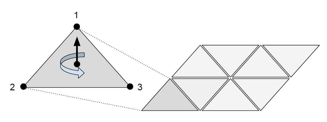
The direction of a triangle's normal is defined by the ordering of its vertices. If the vertices are ordered counter-clockwise when facing the triangle, the triangle's normal is pointing towards the viewer, as shown in the figure above.
The direction of the normals is important for the physics simulation as it indicates in which direction to apply the terrain reaction forces during collisions between rigid bodies and the terrain surface. If a triangle normal is pointing the wrong way, unrealistic reaction forces can occur upon collision with said triangle which would pull the colliding object into the terrain surface rather than pushing it out. The solution in this case is to modify the Graphics Gallery and ensure that the triangle normal directions are consistent with the shape of the terrain and are always pointing out of the terrain's mesh surfaces, such as rocks or buildings, and not into them.
Using the Mesh Normal Visualizer
Unfortunately, it is virtually impossible to find flipped normals by just inspecting the created terrain as the graphical mesh will draw the triangles from both sides, no matter in which direction its normal is pointing. So, even though the terrain will look visually correct, defects might still exist and will only become apparent once strange reaction forces occur in certain terrain regions.
The Mesh Normal Visualizer is designed to help in this regard. It visualizes triangle normals in a user-specified region and uses color coding to highlight surface regions which contain flipped normals.
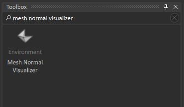
In order to use it in your scene, just add it from the Toolbox, enable its accessory and move it to the terrain area you wish to inspect.
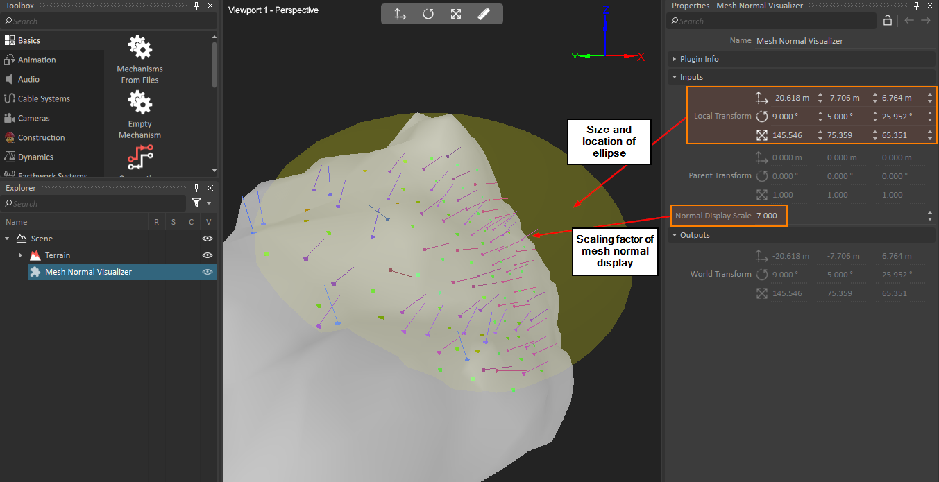
The Mesh Normal Visualizer can be moved and resized with the transformation manipulators. The normals of triangles that fall into the visualizer's ellipsoid (shown as yellow accessory) will be displayed, and will be drawn with a unique color for each possible normal direction. The size of the displayed normals can be changed using the Normal Display Scale input.
Normals pointing in similar directions will have a similar color. This way it is easy to spot flipped normals by simply checking whether significant color variations appear in connected mesh regions. If the surface in such a region appears visually rather flat, but shows color variations in the Mesh Normal Visualizer, it probably contains flipped normals.
Here is an example of a terrain region that does not contain flipped normals.
In this case, the colors of neighboring normals transition smoothly across the terrain surface.
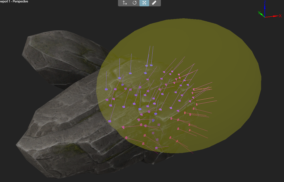
And here is an example of a region in a mesh that does contain several flipped normals.
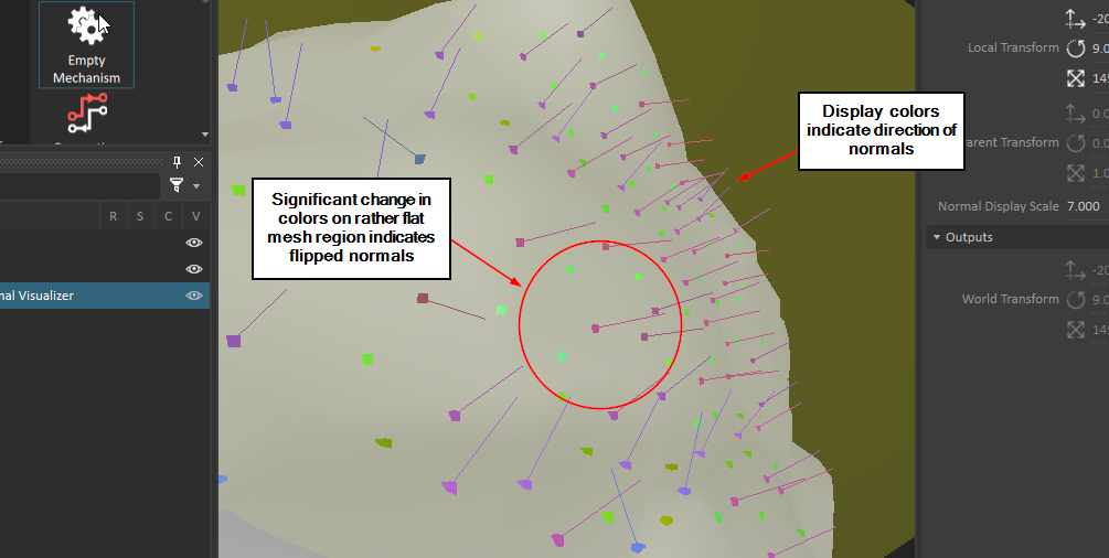
Notice how between the purple normal displays, green boxes (located at the triangles' centroids) appear. The normals of the triangles indicated in green are pointing into the mesh. That's also why their normal vectors are not visible in the display. However, their centroid is still visible, making it easy to spot the issue.
Fixing the error
Once a wrongly oriented, flipped triangle was detected, use your 3D modeling tool to correct the issue in the triangle mesh which was used to produce the Graphics Gallery. Then re-import the gallery and simply re-inspect the terrain. The error should now be fixed.