How to Display Earthwork Zones in Unity
- DEVOPS
Earthwork Zones, dynamically simulated in Vortex Studio, can be rendered in Unity during simulation. When a Earthwork Zone is loaded, a height field prefab is loaded from an asset bundle file located in the same directory as the Vortex file that contains the Earthwork Zone.
Manually creating prefabs and Asset Bundles
To manually create assets for the Earthwork Zone, a Unity project with the Vortex Integration Package is needed (such as VortexUnityTools or your own project), some height field and terrain prefabs must be added and the assets must be packaged in asset bundles.
For an overview of the assets workflow, refer to Workflow for Preparing and Using Assets for a Vortex Simulation with Unity Graphics.
Height Field Prefabs
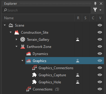
At simulation time, when a Earthwork Zone instance is added, the Vortex Integration will look for a height field prefab with a specific name. The prefab name must contain the Graphics Soil hierarchy with the Graphics Soil name from the Vortex Editor explorer without the parent element that is contained in a Vortex file. The hierarchy levels are separated with period characters. Folders are omitted from the hierarchy. The name and hierarchy are case sensitive.
For example, for the following hierarchy, the prefab name would be Construction_Site.Earthwork Zone.Graphics.
Creating a Height Field Prefab
The height field prefab must have a Vortex Height Field component and a Vortex Height Field Renderer component.
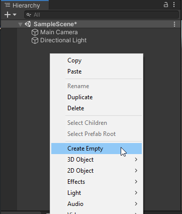
- Create an empty GameObject
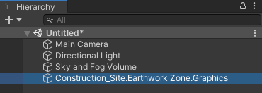
- Rename it with the proper name (see the Height Field Prefabs section introduction)
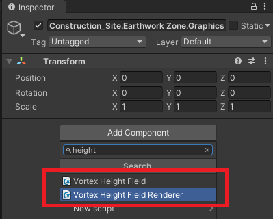
- Select the created GameObject and add the VortexHeightField and VortexHeightFieldRenderer components in the inspector
- Create a new material based on the DefaultHeightFieldShader shader and assign it to the VortexHeightFieldRenderer material field

- Drag and drop the GameObject somewhere in the Assets folder in the project pane to create the prefab
You can create folders in in the assets folder to store the prefabs (ex: Assets/Resources/Scene)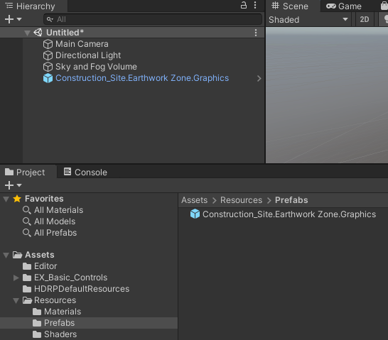
In the following section, we present in great detail the required components and materials that compose a height field prefab.
The VortexHeightField Component
The VortexHeightField component is in charge of managing the height field data and to updating the renderer.
![]()
These public fields can be configured through the inspector:
Field | Description |
|---|---|
| Height Field Offset | An height offset that can be applied to the height field. |
| Hole Offset Factor | An offset factor to shrink down the hole created in the terrain where the Earthwork Zone is located. |
| Blur Enabled | Enables height field geometry smoothing |
| Blur Radius | Sets the smoothing factor on the height field geometry |
The VortexHeightFieldRenderer Component
This component is used to render the height field as a dynamic mesh. The mesh is generated once and updated based on the incoming height field data.
These public fields can be configured through the inspector:
Field | Description |
|---|---|
| Material | The Unity material assigned to the generated height field mesh. The material must be based on the DefaultHeightFieldShader. |
| Terrain Upscaling | Used to create a higher level of visual detail without having to increase the number of Dynamics cells, which can otherwise be computationally costly. |
The Height Field Material
The material must be based on the DefaultHeightFieldShader. To get a seamless transition between the overlapped terrain and the Earthwork Zone un-disturbed soil, the material must use the same parameters as the terrain node it intersects. The disturbed soil look can be controlled independently.
These public fields can be configured through the inspector:
Field | Description |
|---|---|
| BaseMap | The color texture used on the un-disturbed soil. It must use the same texture from the intersected terrain material. |
| NormalMap | The normal texture for the un-disturbed soil. It must use the same texture from the intersected terrain material. |
| Metallic | Determines how “metal-like” the surface is (between 0 and 1). It must match the value from the intersected terrain material. |
| Smoothness | Determines how smooth the surface is (between 0 and 1). It must match the value from the intersected terrain material. |
| Disturbed Soil Albedo | The color texture for the disturbed soil |
| Disturbed Soil Normal Map | The normal texture for the disturbed soil |
| Disturbed Soil Normal Strength | The strength of the normal from the normal texture |
| Disturbed Soil Texture Tiling | The disturb soil texture texture tiling |
| Disturbed Blend Range And Offset | Controls the blending between the disturbed and un-disturbed soil textures. X Value: The range in meters to mix disturbed and un-disturbed soil Y Value: The offset in meters from the disturbed and un-disturbed junctions |
The Enable GPU Instancing, Emission and Motion Vector For Vertex Animation parameters are inherited by Unity's shader graph and should not be enabled.
Creating a custom heightfield shader
A custom shader must be assigned to the Earthwork Zone prefab if a custom terrain shader is assigned to the intersected terrain prefab. The steps to create a custom heightfield shader are:
- Duplicate the custom terrain shader graph
In addition to the described fields in the Height Field Material section, add these parameters to the shader
Reference Name Type HeightFieldTexture Texture2D HeightFieldDimensions Vector2 DisturbedSoilDistanceField Texture2D RemapTexUV0, RemapTexUV1, RemapTexUV2, RemapTexUV3 and RemapTexVertexColor are textures parameters that must also be added if the shader uses vertices UVs or colors.
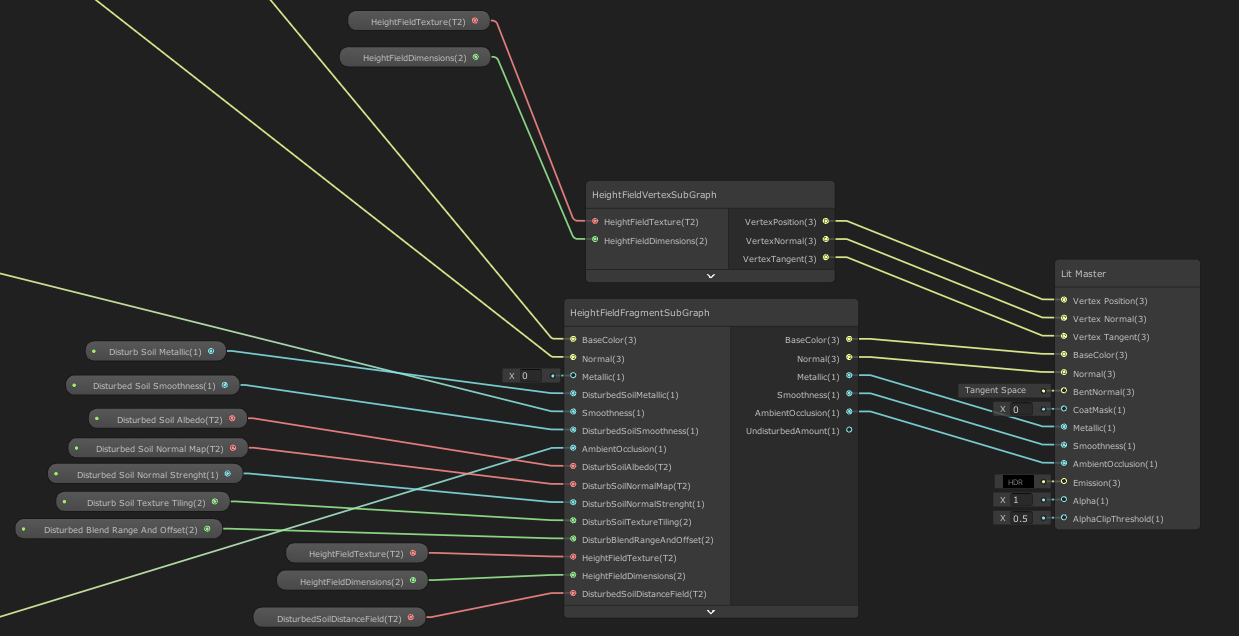
- Insert a HeightFieldVertexSubGraph and a HeightFieldFragmentSubGraph in the shader and link the nodes with the properties nodes and the Lit Master node as shown in this image.
- Modify all samplers that use the mesh UVs to use the UVs stored in the RemapTexUV0, RemapTexUV1, RemapTexUV2 and RemapTexUV3 textures
Before: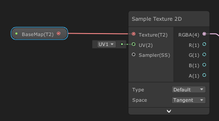
After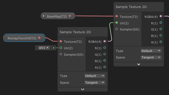
- Replace all Vertex Color nodes to use colors stored in the RemapTexVertexColor texture
Before: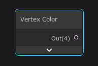
After: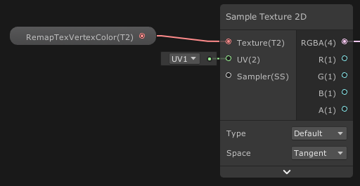
- When creating the material based on the shader, make sure that the parameters common with the terrain material are all set to the same values.
Terrain Prefabs
In order to properly display the height field over the terrain, a terrain prefab must be prepared. The process is similar to the one used for the graphic galleries but the material assigned to the underlying mesh must be based on the TerrainShaderGraph shader or must be a custom shader following specific conventions.
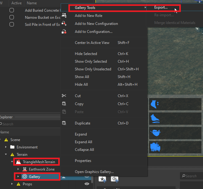
- Open the scene in the Vortex Editor and export the Graphic Gallery used for the File Terrain throughout the Gallery Tools
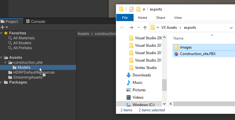
- In the Unity project, create a folder named after the graphic gallery file and drag and drop the exported FBX file and the images folder.
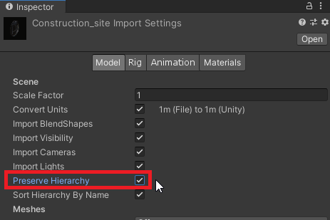
- Select the imported model and make sure that Preserve Hierarchy is checked in the property pane in the Model section
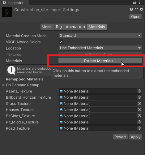
- In Materials property section, click on Extract Materials and select a folder that will contain the extracted materials
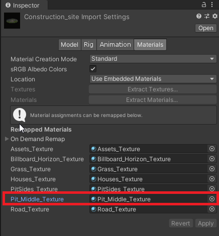
- For each sub-mesh that intersects with the Earthworking Zone, select the corresponding material by double clicking it
- Note witch textures are assigned to the base map and the normal map by clicking on the textures icons
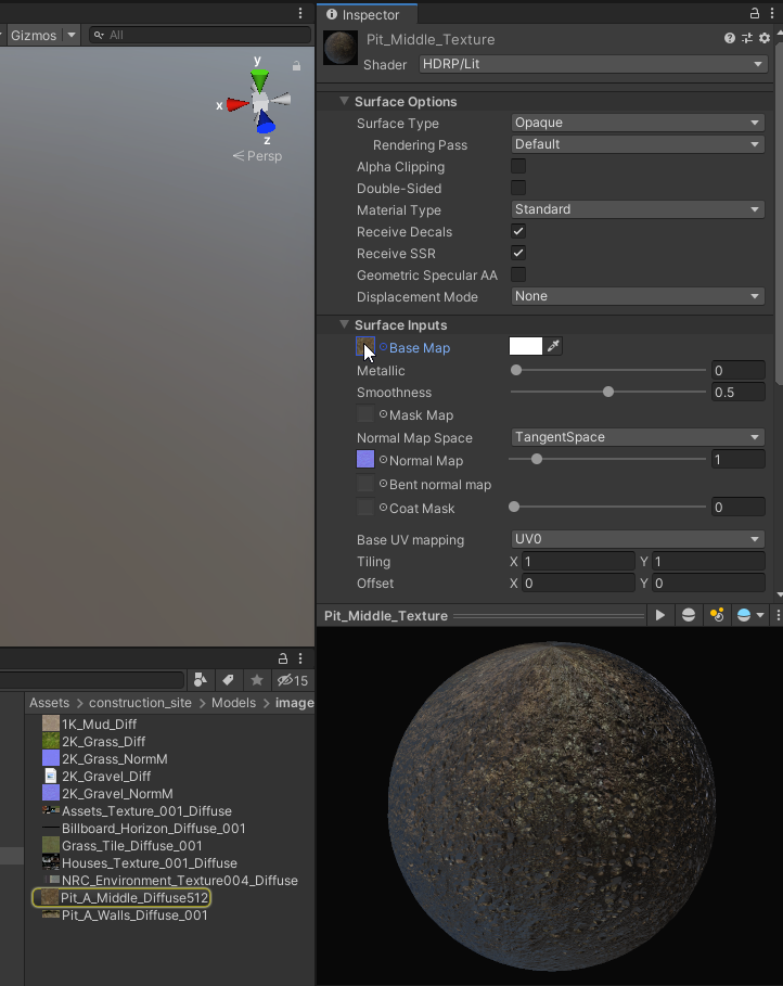
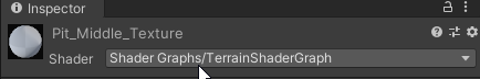
- Change the material shader for TerrainShaderGraph
- Assign back the Base Map and Normal Map textures
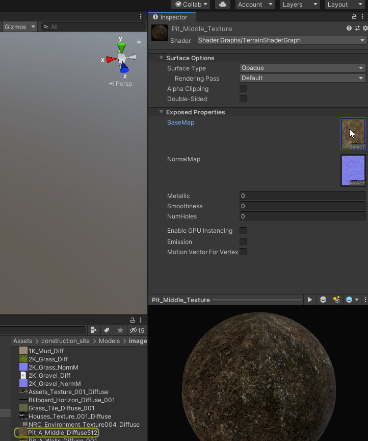
- Enable Alpha Clipping on the material
- Repeat steps 5 to 8 for each material that will be in contact with the Earthwork Zone.
Creating a custom terrain shader
A custom shader can also be assigned to the sub-meshes where the Earthwork Zone intersects. Some rules must be followed:
- The shader must have a Vector1 property name NumHoles set to zero by default. The reference name should also be NumHoles. The property declaration must be overridden to Per Material.
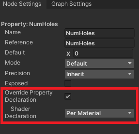
- The shader must have Matrix4 properties HoleTransform00, HoleTransform01, HoleTransform02, HoleTransform03. The reference names should be the same as the properties names. The properties declarations must be overridden to Per Material.
- The shader must include de TerrainHoleSubGraph. The subgraph node should be linked with the properties listed above and with the Master Node Alpha input.
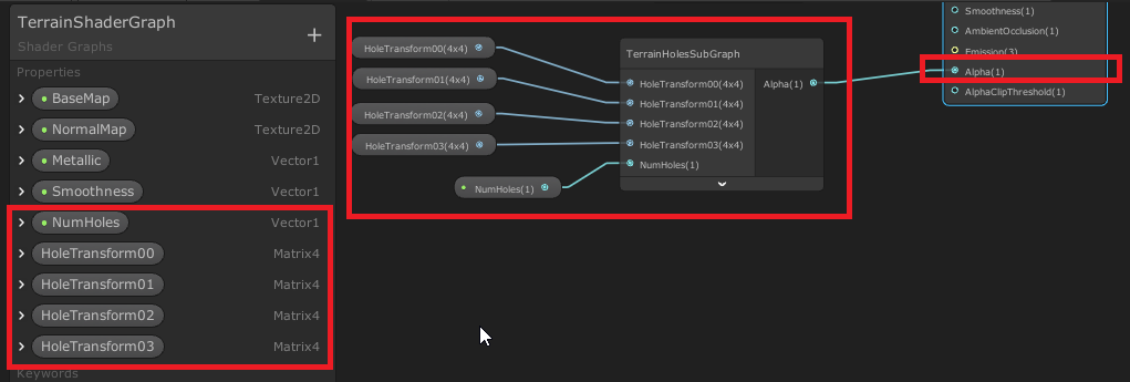
- The AlphaClipThreshold on the master node must be set to 0.5.
- The shader name must contain "TerrainShaderGraph"
- The material that will use the custom shader must enable Alpha Clipping.
Creating an Asset Bundle
Once the height field prefabs and the terrain prefabs are created, they can be packaged in asset bundles so that they can be loaded by VortexUnityApp, or your own similar Unity application with Vortex Integration.
The process for generating an asset bundle is described in this section. In short, you can use the Export Asset Bundle... command from the context menu when selecting the folder containing the prefab's assets.
Then, select the file's destination and name to create the file.
In order to get VortexUnityApp to load the asset bundles properly, the asset bundles files must be placed in the same folders where are stored the Vortex file that contains the Earthwork Zone and the Vortex graphic gallery.