Tutorial: Creating a Vehicle with Modular Vehicle Systems
- DEVOPS
Analytics
In this tutorial, you will learn the basics of the Modular Vehicle Systems by modelling a simple front wheel drive (FWD) vehicle.
Before looking at this tutorial, you should be familiar with Modular Vehicle Systems.
This tutorial will guide you through the steps of creating a complete vehicle, which will be equivalent to a sample vehicle provided in the Vortex Studio Sample package located in C:\CM Labs\Vortex Studio Content <version>\Samples\Vehicles\Car - Hatchback\, where <version> is the currently installed version.
This folder contains a complete vehicle, but also provides the source graphical model and tuning tables used for this tutorial. Note that other complete vehicles can be found under C:\CM Labs\Vortex Studio Content <version>\Samples\Vehicles.
Creating the Chassis
In this step, we import an existing Graphics Gallery into the Vortex Studio Editor and prepare the file for work by adding an assembly to receive the various parts and constraints.
NOTE: In the recommended Vortex workflow, a 3D artist provides the Graphics Gallery and it already contains the required 3D model, along with its meshes, textures and graphics materials.
| Step | Task | Action | References |
|---|---|---|---|
| 1 | Create a new mechanism | From the Vortex Studio Editor Home screen, click the Mechanism box. |  |
| 2 | Rename mechanism to Car | Select Mechanism in the Explorer panel, then either:
| |
| 3 | Save local copy of Graphics Gallery | From the Home page, click Open and select the Car - Hatchback.vxgraphicgallery file located in the Graphics subfolder of the folder mentioned above. Save As a copy of the file in your working folding. | |
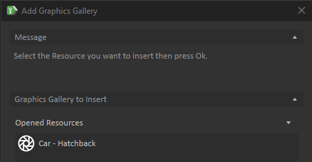
| 4 | Add Graphics Gallery | Switch back to your mechanism's tab. Select Graphics in the Toolbox. Double-click Galleries From Files.... In the resulting panel, select Car - Hatchback and click Ok. (Since you opened the Car Graphics Gallery in the previous step and have the tab open, it will automatically be shown in the Opened Resources section of the Add Graphics Gallery dialog box.) |
|
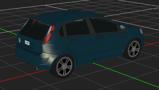
| 5 | Examine Graphics Gallery | In the Explorer panel, the 3D model is located within a Graphics Gallery than can be expanded via the small triangle on the left. It contains the 3D model and all its associated files (e.g., textures). NOTE: The x axis is the forward direction of the vehicle. This is the standard, and all vehicle galleries must follow this convention. NOTE: You can see the various files but cannot change them. To do so, the Graphics Gallery must be opened in a separate window. Leave this aside for now. | |
| 6 | Examine 3D model | You should now see the car model in the centre of the viewport. Follow the next link for more information on how to navigate in the 3D Vies, Using the 3D View . |
|
| 7 | Add assembly | Select Basics in the Toolbox. Double-click Empty Assembly to add it. | |
| 8 | Add part for body | Right-click on the Car Hatchback > Body graphics node in the Graphics Gallery and click Create Part... to create a part in the assembly (this will be the body for the vehicle). | |
| 9 | Save Car mechanism | You can now save the mechanism file by clicking Save. In the resulting browser window, find the desired destination folder, and click Save. | |
| 10 | Add collision geometry | Right-click on the Body part that was added to the Assembly and select Create Collision Geometry > Convex Mesh....Enter Wheel.* in the Excluded Graphics Nodes field so the geometry is created for the body only, not the wheels. In the resulting panel, click Ok to create the collision geometry. In the Explorer panel, Double-click on Assembly to open it in a tab. | |
| 11 | Set material | Click on ConvexMesh_Body. In its Properties panel, select the material Chassis from the dropdown of the Material field. | |
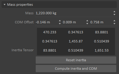
| 12 | Set mass | Click on the Body part in the Explorer panel. In the Properties panel, under the Parameters tab, set the mass to 1220 kg. | |
| 13 | Calculate inertia tensor | Calculate the inertia tensor with the Compute inertia and COM button. |
|
| 14 | Add attachment point | Right-click the Body part in the Explorer panel and select Insert Attachment Point. Rename the attachment point Body [AP] to match the standard naming convention used in modular vehicle. Save and close the assembly. | |
| 15 | Save Assembly | Save and close the Assembly tab. | |
| 16 | Test the mechanism | Test the mechanism to see the vehicle chassis drop to the ground. |  |
Add the Modular Vehicle Topology File
In this step, we add an existing vehicle topology to the mechanism.
Topology files define which components exist in a vehicle, how they are connected, and some additional logic common to the vehicle. However, the actual properties and tuning of the vehicle (dimensions, mass properties, torques and gear ratios) are defined by the user using the interfaces defined in the topology file. This allows the topology to be used and tuned for many different specific models of vehicles. For example, RWD topology file can be used and parameterized to model a sedan, a pick-up truck, or a single-axle dump truck, simply by changing the values in the topology interface.
Topology files are standard Vortex assemblies that are included with the Vortex Studio Sample package located in C:\CM Labs\Vortex Studio Content <version>\Samples\Vehicle Systems\Topology
| Task | Action | References |
|---|---|---|
| Add vehicle topology file | Select Basics from the Toolbox. Double-click Assemblies from Files. Click the Browse button and navigate to the FWD folder of the Topology directory listed above. Select the FWD.vxassembly file and click Open. |
Defining the Component Configuration
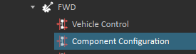
Every vehicle topology contains a Component Configuration interface, which contains parameters to set the relative positions of all components, some properties that are common to all components, and a field to specify a user body to attach to the vehicle chassis.
The steps below refer to the fields in the Component Configuration interface in the FWD sub-assembly.
| Step | Task | Action | References |
|---|---|---|---|
| 1 | Read Wheel Positions | If the exact wheel positions are known, they can be directly entered in the Component Configuration. In this case, they can be read from the graphics gallery. In the Explorer window, click on the wheel node in gallery at Car Hatchback → Body → Wheel FL. In the Properties window, look at the Outputs -> World Transform field. The top row of values are the (x, y, z) position of the wheel: (1.177, 0.765, 0.336) Note the same values for the Wheel RL wheel. All are the same except the x value: -1.436 | |
| 2 | Set Wheel Positions | Navigate to the Component Configuration interface of the FWD sub-assembly. The Wheel Position Front field corresponds to the x position of the front wheels, which was read in the previous step: 1.177 The Wheel Position Rear field corresponds to the x position of the rear wheels: -1.436 The Wheel Spacing field is the width between wheels, which is double the y position of the wheels: 0.765 * 2 = 1.53 The wheel height is the z position of the wheels: 0.336 With these values set, the centres of the collision geometries of the wheels should now match the gallery. |
|
| 3 | Set Body Attachment Point | Set the Body Attachment Point field to the attachment point added to the Body part. Drag the Body [AP] attachment point from the Body part directly onto the Body Attachment Point field. |
|
Creating the Collision Rule
In this step, a collision rule is created to prevent the various parts of the vehicle from interfering with each other.
| Step | Task | Action | References |
|---|---|---|---|
| 1 | Test mechanism | Start the simulation. Try dragging the vehicle around, and notice that the wheels are locked. This is caused by the wheels colliding with the body of the vehicle (activate the contact display Shift+C). Stop the simulation. |
|
| 2 | Add collision rules container | Select Basics from the Toolbox. Double-click Collision Rule Container. |
|
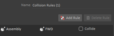
| 3 | Create collision rules | In its Properties panel, create a new Collision Detection Rule by clicking on Add Rule. In the new rule, drag the Assembly to one side, and the FWD sub-assembly to the other. Ensure that Collide is not clicked, so that there is no collision between the Assembly and the FWD. |
|
| 4 | Test mechanism | Start the simulation. Try dragging the vehicle around, and notice that the wheels now roll freely. Stop the simulation. | |
| 5 | Save mechanism | Save the file. |
|
Connecting Wheel Graphics
In this step, the graphics are connected to the wheel physics parts so that they correctly show the state of the simulation.
| Step | Task | Action | References |
|---|---|---|---|
| 1 | Open Skin Connection Container | Note the Skin connection container that was created when the body part was created. Double click the Skin container to see a graph of connections between parts and graphics nodes. | |
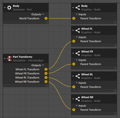
| 2 | Connect wheel transforms to nodes | Click on the FWD -> Part Transforms interface. This has fields that output the current transform for each part in the vehicle sub-assembly. Drag each of the four Wheel Transform fields into the graph window. These correspond to the four wheels: front left (FL), front right (FR), rear left (RL) and rear right (RR). Expand the gallery to see the four wheel nodes in Car Hatchback -> Body -> Wheel FL. Click on each of the wheel nodes and drag the Parent Transform field to the yellow circle of the corresponding Wheel Transform in the graph. This creates connections that send the live values of the transforms of each of the wheels to the nodes of the graphics gallery, so they move with the physics simulation. |
|
| 3 | Test mechanism | Start the simulation. Try dragging the vehicle around, and notice that the wheel graphics now correctly roll with the parts. Stop the simulation. |
|
Set Basic Component Properties
While there are many parameters that need to be set to correctly model a particular vehicle, the steps below outline the bare minimum needed to get a functional vehicle.
| Step | Task | Action | References |
|---|---|---|---|
| 1 | Copy Table from Samples | Two tables in the sample vehicle will be used for this tutorial. Copy the two .csv files from the Tables subfolder of the Car - Hatchback sample directory into your own vehicle directory. | |
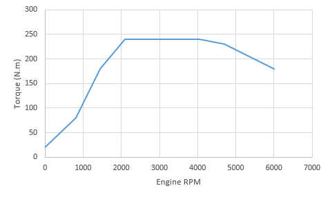
| 2 | Set Engine Torque Table | Click on the Engine Tuning interface in the FWD sub-assembly The Torque Table needs to be provided for every vehicle. This is a single curve of torque as a function of engine RPM. The curve can be many points for smoother operation, or can be as little as two points (such as max torque and max power) if that all that's available. Click on the ... button of the Torque Table parameter. Choose the Engine Torque Table.csv file that was previously copied into your user directory. |
|
| 3 | Set the Idle RPM | The Idle RPM parameter should match the stable RPM of the vehicle when in neutral and no throttle is applied. Set the value to 800. | |
| 4 | Set the Torque Converter Stall Point | Click on the Coupling Tuning interface. The Stall RPM and Stall Torque determine the point at which the torque converter will fully couple the engine to the transmission. In general, this will be near the maximum torque point of the engine curve. For this vehicle, set the Stall RPM to 2100 and the Stall Torque to 240. | |
| 5 | Set the Transmission Gear Ratios | These correspond to the gear ratios of the transmission. Click on the Transmission Tuning interface. Click on the ... button of the Gear Ratio Table parameter. Choose the Automatic Transmission Ratios.csv file that was previously copied into your user directory. | |
| 6 | Set the Shift Points of the Transmission | There are several fields that determine the automatic shifting behaviour of the transmission, which are described in this section of the documentation. In this case, we only need to set the Shift Scale field to match the maximum RPM of the engine: 6000. When set this way, the Shift Up and Shift Down values will be scaled to shift at a given fraction of the maximum RPM. | |
| 7 | Set the Wheel Values | Click on the Wheel Front Tuning interface, then control-click on the Wheel Rear Tuning interface to select and edit both at the same time. Set the Radius and Width to match the size of the wheel: Radius = 0.337, Width = 0.225 Note that the wheel collision geometries now match the size of the graphical wheel. |
Assigning Wheel Models
While tires in vehicle systems can use normal contact and friction models, they can also be defined to use more advanced soft or hard ground models, which are discussed in Working with Tire Models. These models are defined by adding a tire type and models to the vehicle mechanism, then connecting it to the wheel interfaces.
| Step | Task | Action | References |
|---|---|---|---|
| 1 | Add a Tire Type | In the Toolbox under the Tire Model group, double click the Tire Type extension to add it to your Car mechanism. |
|
| 2 | Add a Tire Model | Right click on the newly-created Tire Type and select Add Tire Model Coulomb | |
| 3 | Rename the Tire Model | Select the Coulomb tire type, then select the Name property, type "Pavement - Default" and press enter. | |
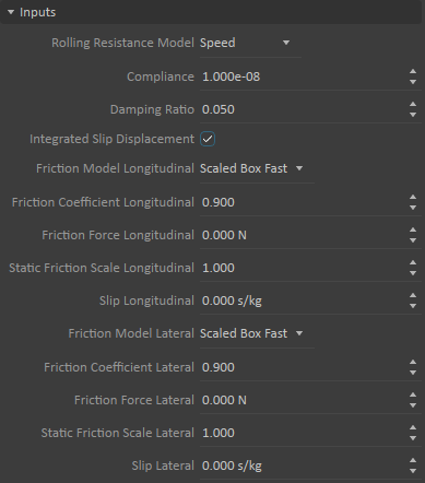
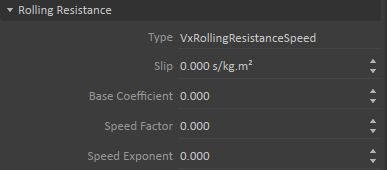
| 4 | Set Tire Model Properties | Enter the values in the Inputs and Rolling Resistance properties as seen in the screen capture. This will define the behavior of the wheel to be equivalent to rubber on pavement. |
|
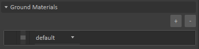
| 5 | Set the Ground Material | In the Ground Materials section, click the + button to add a ground type, and select default in the field. This contact model will be used any time the wheel is touching a collision geometry with a material listed in this Ground Materials list. 'default' is a special value that means this model will be used for all materials that are not otherwise defined in other Time Models. |
|
| 6 | Select the Tire Type in the Wheel interface | Select the Wheel Front Tuning interface in the FWD sub-assembly - > Wheel Front Tuning. Drag the Tire Type object from the Explorer panel to the Tire Type field of the Properties panel. Repeat for the Wheel Rear Tuning interface. |
|
| 7 | Verify the Tire Model is Working | The wheel components provide an interface to test and debug that the wheel models are functioning correctly. Navigate to the wheel component in FWD - > Components - > Wheel FL - > Wheel Contact. Start the simulation. Verify that the Tire Model Name output shows "Tire Type / Pavement - Default", which indicates that our tire model is being used correctly. Note that there are many details about the current state of the tire type shown in this interface. Stop the simulation. |
|
Creating a Driving Interface
All mechanisms should have an interface defined, which is used to control the machine when the mechanism is added to a scene. This step goes through the process of creating a VHL Interface, which provides the inputs and outputs needed to drive the vehicle.
While this vehicle will be controlled through these fields, many vehicles could instead be controlled by hardware devices (eg. gamepad, steering wheel, pedals), which would mean defining the logic and signal processing to connect those devices to the vehicle controls. This is further explained in the following tutorial.
| Step | Task | Action | References |
|---|---|---|---|
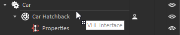
| 1 | Add a VHL Interface | From the Toolbox, choose the Simulation category. Drag a VHL interface from the Toolbox into the Explorer tree just above the Car Hatchback gallery. This places the interface at the top of the explorer tree so it is the first thing seen when using the vehicle in a scene. |
|
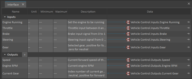
| 2 | Add the Fields to the Interface | When adding the VHL Interface, the Interface Editor opens in the main window. In the Explorer tree, click on the vehicle control interface in the FWD sub-assembly - > Vehicle Control. Click on the Engine Running input in the Properties panel, then shift-click on Gear to select all the input fields. Drag the fields to the Inputs row of the Interface Editor panel. Do the same with the Outputs by selecting all of them and dragging them to the Outputs row of the Interface Editor panel. Close the Interface Editor by clicking the small x on the tab at the top of the Interface Editor panel. Click on the Interface in the Explorer tree and note that it now shows all of the properties needed to control the vehicle, and these will be visible and accessible from the top of the Explorer tree for this mechanism. |
|

Driving the Vehicle
The vehicle is finished and can now be tested and driven using the Vehicle Interface just created in the previous step.
| Task | Action | References |
|---|---|---|
| Test mechanism | Start the simulation. Click on the Interface object in the Explorer tree. In the Properties panel, click on Engine Running to start the engine. Set the Gear to 6 to engage the transmission. Set values in the Throttle, Brake, and Steering to drive the vehicle. Stop the simulation. |
|