Simulator Deployment Tutorial 5: Creating a Custom HMI
This module introduces the steps involved in creating a custom vehicle HMI in Vortex® Studio, by using QtDesigner. This HMI can be used within the Editor, or be deployed to a simulator and used on a touchscreen for human-in-the-loop testing.
Prerequisites
- Before starting this tutorial, we recommend that you have the Basics of Vortex Studio covered first.
- You must have Vortex Studio, Vortex Studio Samples and Vortex Studio Demo Scenes installed to be able to complete this tutorial.
What is the QtDesigner Page?
The QtDesigner Page provides the base for creating a user interface page that connects to the simulation. Such user interfaces are necessary to allow user interaction with the simulation; for a particular device or machine, like clicking a button to start the engine, or for manipulating the scene setup, like dragging a slider to change a weather setting. The Qt pages in the user interface comprise an interactive UI that adds an additional layer of realism to the simulation and allows users to interact with and receive feedback from the simulation.
QtDesigner Page is added as part of the simulation content and is a role feature that can be added to a specific role in the simulation.
Usage of QtDesigner Page
There are several steps involved in the setup and configuration of an interactive UI that can be summarized as follows:
- Create a Qt UI file and populate it with Vortex custom widgets
- Add QtDesigner Page to the simulation content and populate input and output fields from the UI file
- Connect page fields for controls to the simulation content
Creating the UI File
- Under the default file path C:\CM Labs\Vortex Studio 2020b\bin, open designer.exe . This is the software used alongside Vortex to build graphical interfaces for use with Vortex software.
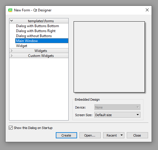
- Upon opening the software, a "New Form" dialog box will appear. Ensure that Main Window is selected, and the Screen Size is set to "Default size". Press the Create button.
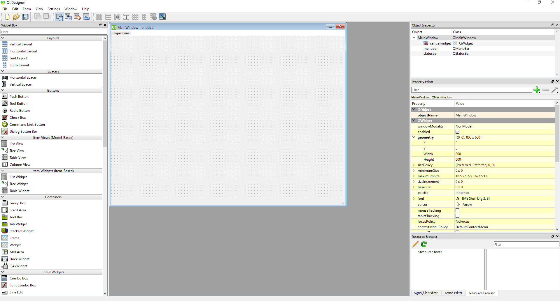
- After pressing Create, a white box will appear in the center viewport. This is the blank slate that will be used to create the UI. The layout of this software is as follows:
- On the left, the Widget Box is where pre-made UI elements can be selected and added to the UI in the center of the screen. Here you can choose from default widgets as well as our custom Vortex related widgets.
- On the right, the Object Inspector shows what UI elements are present in the design.
- Below the Object Inspector, the Properties menu allows precise modifications of each detail of the UI being created.
- Below the Properties menu, the Resource Browser shows relevant directories where important resources may be located.
- First, if not set already, in the Properties panel, expand the "geometry" section and modify Width to 800, and the Height to 600.
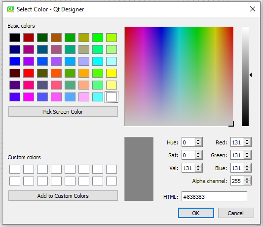
- Right-click anywhere in the MainWindow window, and select "Change styleSheet".
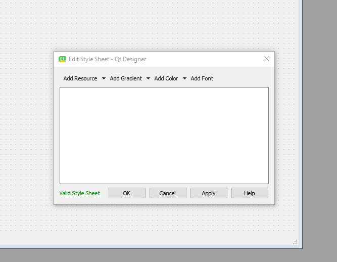
- In the dialog box, select the drop down arrow to the right of "Add Color" and select "background-color".
- Adjust the vertical slider on the right side of the dialog box to make the background light grey. Press "OK" in both open dialog boxes.
- In the top left corner, under File, click Save As... and save the UI file to your working directory, naming it "UITutorial.ui".
Adding Interactivity to the UI
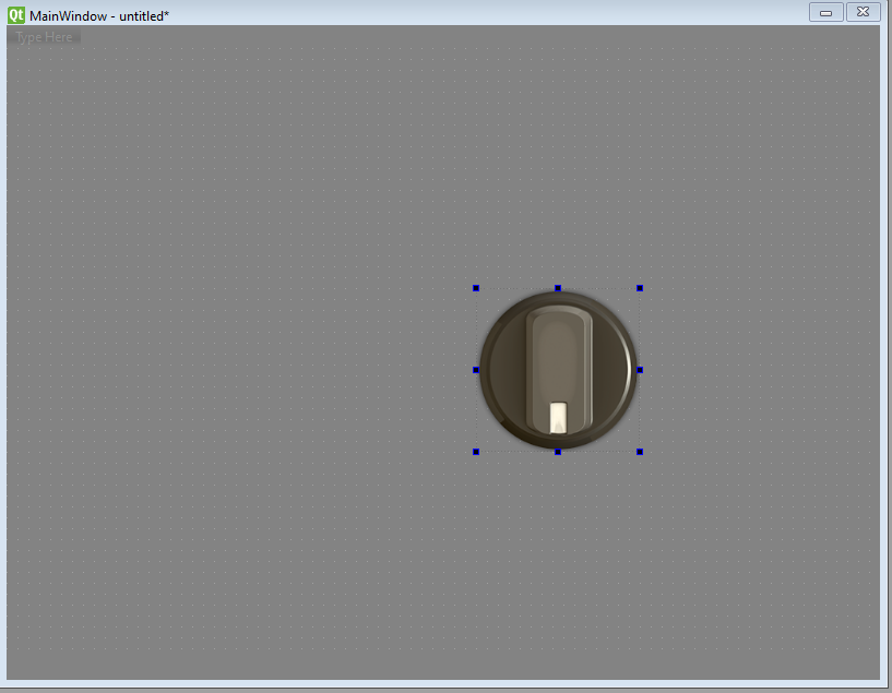
- From the Widget Box on the left-hand side of the screen, drag and drop from the "ConsoleWidgets" section, a "Console::CustomDial" onto the MainWindow.
- Notice that this dial does not have any graphics associated with it. While it does exist and would work, it would render as invisible in the UI.
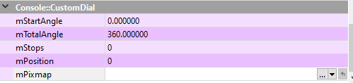
- In the Properties of the Custom Dial, scroll down to the last section named "Console::CustomDial".
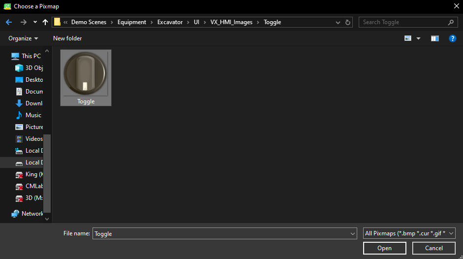
- Under "mPixmap" click on the down arrow to the right of the tab and select "Choose File...".
- Under the default file path C:\CM Labs\Vortex Studio Content 2020b\Demo Scenes\Equipment\Excavator\UI\VX_HMI_Images\Toggle, select Toggle.png
- In the same section of Properties, change the mStops value to 10.
- At the top, under the QWidget section in the Property Editor, set the Width and Height values to 150.
- In the toolbar at the top left of the screen, select Form and click on Preview (Ctrl+R) to preview how the UI will work in practice.
- Click and drag the dial and watch how it rotates.
- Change the mStops value to 60 and see how each increment of rotation becomes smaller as you increase the mStops value.
- Change the mTotalAngle value to 270 (deg) and preview (Ctrl+R) the UI. Notice how the maximum angle of rotation that the dial can turn to, is now 270 degrees.
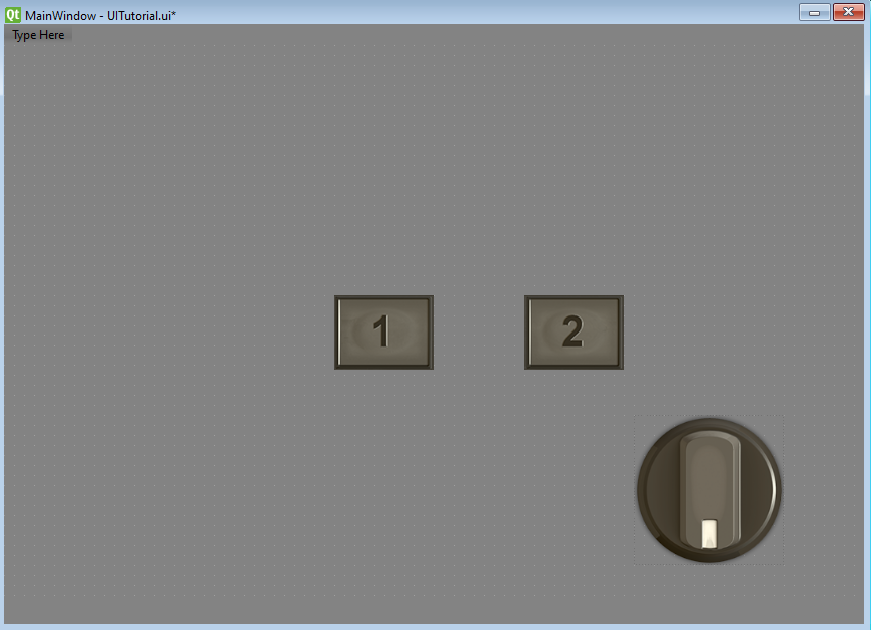
- Drag the dial to the bottom right corner of the MainWindow UI window.
- From the Widget Box, drag and drop a "Console::LampButton" to the Main Window. This will add the functionality of a basic ON/OFF button.
- Once again, this will not have any visuals by default; we will add them now.
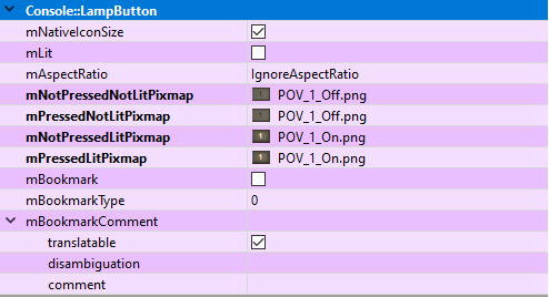
- In the Properties of the Lamp Button, scroll to the bottom, to the "Console::LampButton" section.
- In "mNotPressedNotLitPixmap", click on the down arrow to the right and click "Select File..." and from the default directory C:\CM Labs\Vortex Studio Content 2020b\Demo Scenes\Equipment\Excavator\UI\VX_HMI_Images\POV, select POV_1_Off.png. Match the following procedure for the other properties below:
- mNotPressedNotLitPixmap : POV_1_Off.png
- mPressedNotLitPixmap : POV_1_Off.png
- mNotPressedLitPixmap : POV_1_On.png
- mPressedLitPixmap : POV_1_On.png
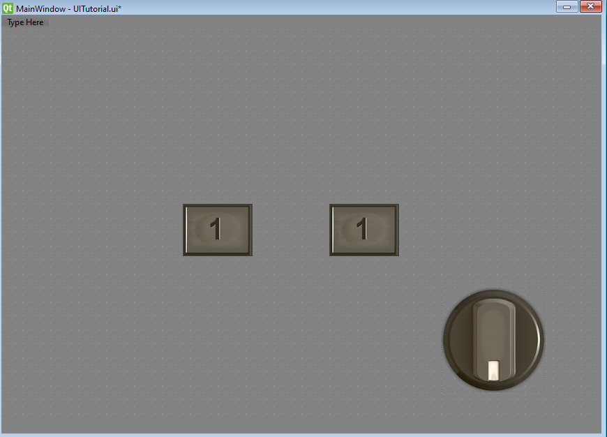
- At the top of the Properties menu, change the Width and Height of the Lamp Button to 100 and 75, respectively.
- Copy the Lamp Button by pressing (Ctrl+C) and paste (Ctrl+V) into the Main Window.
- In the Properties of the new button, change the texture of the button as follows:
- mNotPressedNotLitPixmap : POV_2_Off.png
- mPressedNotLitPixmap : POV_2_Off.png
- mNotPressedLitPixmap : POV_2_On.png
- mPressedLitPixmap : POV_2_On.png
Save the UI file.
Note
If you preview the UI (Ctrl+R), the buttons will appear to not change when you click on them; do not panic. They are actually transmitting data that they've been clicked (0 when not clicked, 1 when clicked), but they are not animated yet. We will animate them when we import the UI to the Vortex Editor.
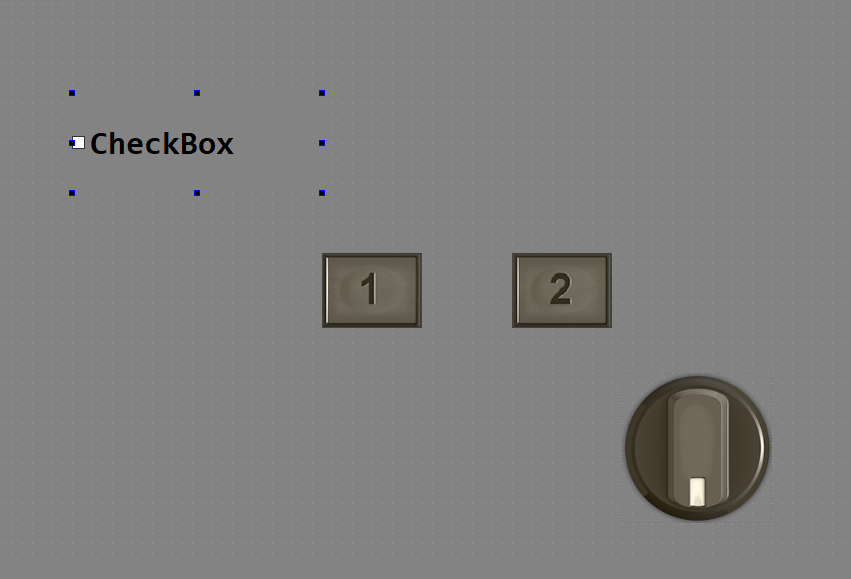
- Next, drag and drop a Check Box from the Widget Box into the main window.
- In the QWidget section of the Properties, change the Width and Height of the Check Box to 275 and 100, respectively.
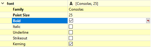
- In the same Properties section, scroll down to the "font" section and change the Point Size to 25.
- Additionally, change the font from it's default of "MS Shell Dlg 2" to "Consolas" by clicking on the three dots next to the font property.
- Make the text Bold by clicking the Bold property underneath Point Size.
Double-click on the check box in the main window, and change the text to "Headlights".
Now, we will add one final component to the UI. Drag a Horizontal Slider into the main window.
- In the QAbstractSlider section of the Horizontal Sliders properties, change the minimum and maximum values to -1 and 1, respectively.
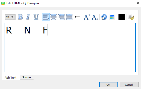
- Lastly, drag a "Text Edit" box from the Widget Box and place it above the Horizontal Slider.
- Set the Width to 180 and the Height to 70.
Double click on the Text Edit Box, and copy & paste (Ctrl+C, Ctrl+V) the following:
R N F
Then, set the font size to 28.
Note
You may have noticed that a dial and a slider have similar functionality. They both offer the ability to move the position of a UI element between maximum and minimum values.
- Since the Dial and the Horizontal Slider offer similar functionality, we will delete the Dial.
- Select the Dial in the Main Window and press the Delete key.
- Save the UI file.
Importing the UI to Vortex
- Open the Vortex Studio Editor.
- From the default path C:\CM Labs\Vortex Studio Content 2020b\Demo Scenes\Equipment\Forklift_Medium\Dynamic\Design, open Forklift.vxmechanism.
- Save this mechanism as a copy in your working directory, as to not overwrite these files since they are needed in other tutorials.
- From the Basics section of the Toolbox, create a Folder and rename to it "HMI".
- From the Basics section of the Toolbox, create a new Connection Container.
- From the Console Pages section of the Toolbox, create a new QtDesigner Page.
- Drag and drop the newly created Connection Container and QtDesigner Page to the HMI folder.
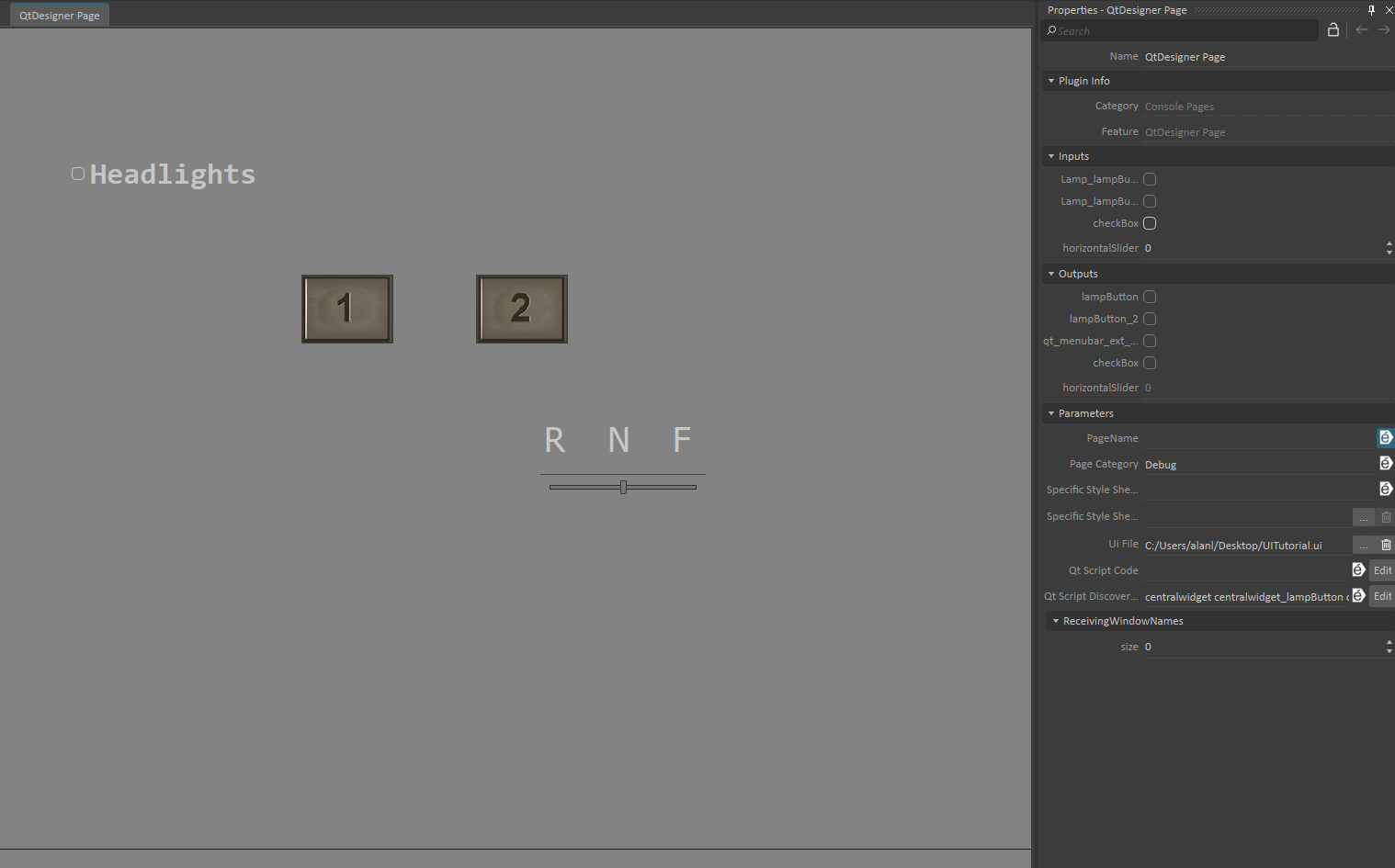
- In the Properties of the QtDesignerPage, under Parameters, click on the three dots to the right of "Ui File" and select the UI file saved from the last section of the tutorial.
- Now, switch tabs to the Connection Container, while keeping the Properties of the QtDesigner Page open.
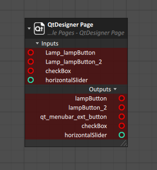
- Drag and Drop all of the inputs and the outputs of the QtDesigner Page into the Connection Container.
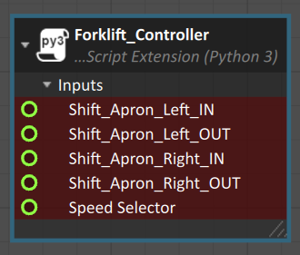
- In the Explorer, open the Scripts folder and select the Forklift_Controller.py script.
- Drag and drop the following Properties of the script to the Connection Container:
- Speed Selector
- Shift_Apron_Left_IN
- Shift_Apron_Left_OUT
- Shift_Apron_Right_IN
- Shift_Apron_Right_OUT
- In the Explorer, in the Forward Spotlights folder, drag and drop the Visible property from each spotlight into the Connection Container.
Connect the modules according to the table below:
Input Output Visible (Spotlight_R) checkBox Visible (Spotlight_L) checkBox Speed Selector horizontalSlider Shift_Apron_Left_IN
lampButton Shift_Apron_Left_OUT lampButton_2 Shift_Apron_Right_IN lampButton Shift_Apron_Right_OUT lampButton_2 Lamp_lampButton lampButton Lamp_lampButton_2 lampButton_2 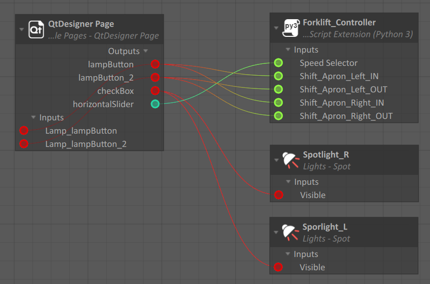
Note
Yes, the both lamp buttons output to three inputs. Each button will do three things at once; shift the left and right aprons in/out, and light up. The reason why the lamp button is an output for itself is to tell the button to light up once it is pressed.
Save the mechanism.
- Now it is time to test out the UI. Start the simulation by pressing the play button at the top of the screen.
- By switching between tabs, turn the headlights on and off and note the results.
- Shift the forklift into Forward gear. Note that to go into reverse, you must drag the slider all the way to the opposite side, then back to Neutral position. From there you can move into Reverse gear or back into Forward gear.
- Press and hold the "1" button for a few seconds. Switch tabs and notice the forks are close together.
- Press and hold the "2" button for a few seconds. Switch tabs and notice the forks are far apart.
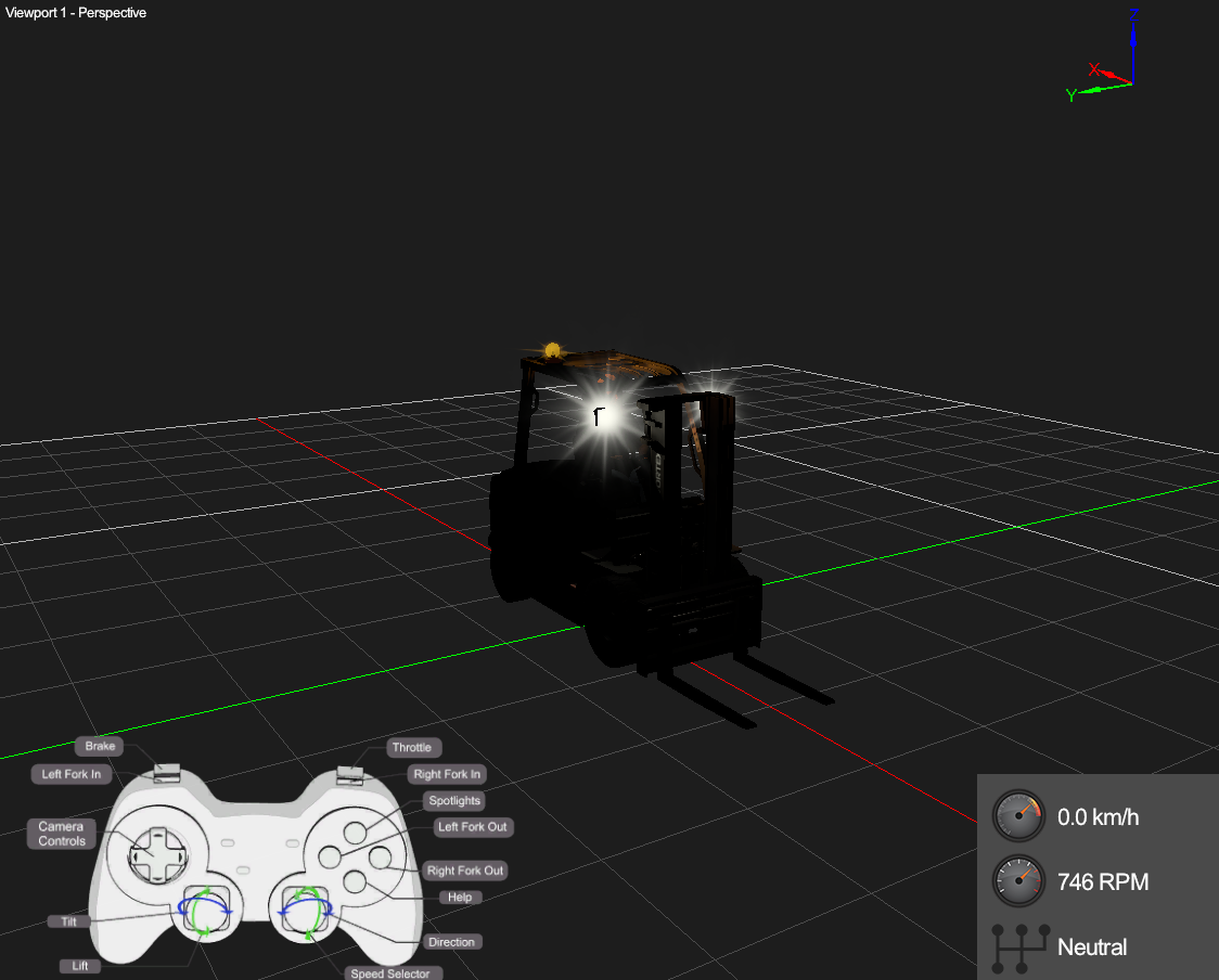
- We now have a functioning UI for the forklift! This is only a glimpse into what is possible through a Vortex UI. It should be noted that this mechanism was not created with a UI in mind; with more careful mechanism creation much more in-depth UI functionality is possible.