Texture Creation
- DEVOPS
Textures are usually created in Adobe Photoshop or GIMP, though it's possible to use many other image DCCs.
Textures need to be square and at a resolution set to a power of 2 (2x2 all the way to 4096x4096 pixels).
Similar to the polygonal budget, a texture budget should use higher resolution textures near the user and reduce resolution as distance increases.
Six main texture types, or channels, are supported by the Vortex® Studio Editor.
- Emission maps are self-lit textures that are used to define lit areas such as building windows or car headlights.
- Occlusion maps (also known as shadow maps) represents the ambient occlusion of the model.
- They usually get their own separate UV set so the seams will fall within occluded areas.
- Albedo maps comprise the main coloring of the model.
- They can include baked shadows and transparency (though these usually get their own maps or materials).
- If the texture includes baked shadows and transparency, it is called a Diffuse map (but is still inserted in the Albedo channel).
- Specular maps are used to define how much light is reflected, and where.
- Gloss maps are used to define areas that are shiny or matte.
- Normal maps are used to simulate geometric details by displacing pixels without adding triangles.
- These are often created using a high resolution version of the model and baking it to a lower resolution version.
- The baked information gives the impression that more geometry is present.
For the texturing of the model, an atlas containing all of the albedos in one texture file can be applied to the major parts.
In the following image, a rock surface texture set that includes Albedo/Diffuse, Specular and Normal maps is shown.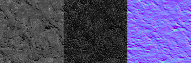
Unwrapping
Completed models need to be UV unwrapped. This involves laying all the surfaces out flat in order to create the texture. The major surfaces are separated and packed tightly into a square space called the UV map.
UV represents the coordinates in 2D of the unfolded surface of a 3D model, allowing the application of a 2D texture on a 3D object in a 3D world. U and V are used to avoid confusion with (x, y, z) used for space coordinates.
It is important to plan the locations of seams (where the edges of the textures will meet) ahead of time. Sometimes, it is necessary to force an additional texture seam by creating a physical edge, line or seam in the right place on the 3D model.
UV Sets
By default, most 3D modeling software will create one UV set for a 3D model. However, additional UV sets afford more flexibility to the user in how to apply textures to a model.
Separate UV sets can allow emphasis to a particular 3D component, which would not be possible within a single large UV. Adding more UV sets must be done in the 3D modeling software before being imported into Vortex® Studio Editor.
A 3D model can be broken down into as many UV sets as desired, though Vortex® Studio supports a maximum of four.
Consider the following UV map example.
Note The artist can reserve larger UV areas for parts that need a higher texture resolution.
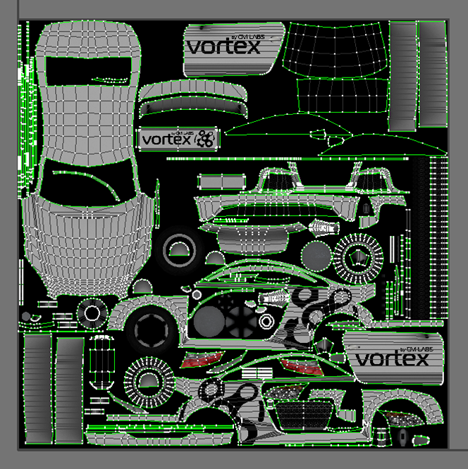
The logos have a large space so that the resolution is clear enough. Smaller, or less important parts can use less UV map space. For really small details, however, it's usually better to place them on their own, dedicated UV.
Fitting all the texture elements into one sheet requires planning. Elements of the same color should be grouped together to prevent bleeding when the texture mipmaps to a lower resolution.
Note Since textures are projected onto the model, it's critical to correctly manage the triangles in face mode with the polygon edit tools in the 3D modeling software, so the textures will follow the surfaces correctly and not deform or stretch.
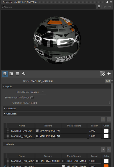
Multi-texturing
One method of creating realistic-looking graphics models is through multi-texturing. It is possible to layer multiple maps and use some of them as masks to create a very rich appearance.
Note Multiple UV sets are a tool for multi-texturing but are not required for it. It's possible to layer multiple texture maps and masks onto a single UV set.
Procedural Object Textures
Some graphic assets do not have an associated 3D model because they are generated procedurally in the course of the simulation. They still require graphic materials and textures in order to be visualized.
The Vortex® Studio Editor comes with some chain and strap textures. If a unique texture is needed, a variant can be created by artists as required.
Particle Textures
Particle textures are used to help determine the visual appearance of particle effects, such as dust, rain or smoke. Most of the time, the textures have transparent areas around the particle itself.
By using a script to modify the offset, tiling and orientation parameters of the textures, it's often possible to create animation effects within a particle cloud or spray.
See Soil Dust Extension for more information.
Soil Textures
These are used to help determine the visual appearance of soil and soil particles in the Earthwork Systems. They are often the same textures used for the terrain 3D model, or are modified from them. They usually need to tile.
See Earthwork Systems for more.
Cable Textures
Cable textures help determine the visual appearance of cables, catenaries, and pipelines. They usually need to tile. Most of the time, they are opaque, but it's possible to need some transparent areas (to create chain-like cables, for example, or barbed wire).
A chain texture consists of a single link, with empty space on either side. This space is used as an offset when the chain is created to ensure an even visual spacing of the links.
See Cable Systems for more.
Transparent Textures
Transparent parts, such as windshields and cabin windows, usually get their own transparent graphic material. Nonetheless, it's possible to create and import textures with some transparent areas in them.
When a texture with transparency is required, for trees or billboards, it is important that the transition be explicit. This means there must not be any tones of gray between the opaque and transparent parts of the image. Any gray colored or smoothed zones will cause visual artifacts at runtime.