The Multi Body Dynamics module includes the following physics, collision detection, and solver features. For more information regarding the theory that underlies the Vortex Studio MBD module, please refer to the Vortex Theory Guide Document.
Core Dynamics
- Full collision response and dynamic response, with minimal CPU overhead for calculations.
- Vortex Studio calculates contacts between rigid bodies, adds constraints, and simultaneously solves full constraint systems including kinematic loops.
- Objects can be modified, extended, assembled, and disassembled at runtime.
- Assign object properties such as mass, inertia, center of mass.
- Define material interaction properties such as friction, stiction, and restitution in physically meaningful units.
- Most object and interaction properties can be modified at runtime.
- Support for multiple friction models ranging from frictionless to scalable approximation of Coulomb friction enables users to balance efficiency with accuracy.
- Anisotropic friction allows objects to have different friction properties for different directions.
- Choose between multiple solvers optimized for precision versus speed.
- Scalable contact response capable of simulating large numbers of objects in real time.
- Contact generation algorithm based on the volume of intersection between colliding geometries (instead of only on boundary intersections) for improved stability, particularly in large area and stable contact situations (such as in grasping, docking, etc.).
- Kinematic and dynamic constraints, including multi-body constraints that can be added, removed, and reconfigured at runtime.
- Multiple constraint types such as ball and socket, hinge (revolute joint), spring, and distance; various vehicle suspension constraints; and advanced constraints allowing users to precisely control relative linear and angular degrees of freedom.
- Constraint degrees of freedom can be motorized (limited in velocity), locked (limited in position), or free — all with or without compliance and motion range limits
- Support for high constraint stiffness
Collision Detection
- Object collision detection between large numbers of objects and the terrain.
- Geometrical primitives, terrains, and complex polygon meshes. Vortex Studio computes contact points, normal and penetration, with optional support for fast-moving objects and time-ofimpact calculations.
- Automatically generate convex meshes from any type of triangle mesh model using HACD or VHACD convex decomposition algorithms.
- Optimized for speed: objects are automatically separated into groups — objects that are close to each other and need to be checked for collision or interference versus objects that are far apart and do not need to be taken into account.
- Efficient handling of large numbers of objects, and optimized object insertion and removal.
- Collision pairs can be disabled for maximum user control over specific behaviors.
- Level of detail: objects can be represented by meshes of varying complexity, or by simpler collision primitives.
- Event handling: persistent user information for colliding pairs allows users to schedule events based on collision or separation.
- Support for a large number of collision types such as geometric primitives, convex mesh, triangle mesh, plane, and height field.
- Sensors and Triggers for intersection detections and ray casting available in the Editor and through the API.
o Collision detection data between collision geometries is available o Sensors and triggers can be activated or deactivated at run-time o Tutorial available to show how to customize reporting extension
- Part Distance Sensor and Geometry Distance Sensor extensions measure the closest distance between parts or collision geometries, respectively.
Solvers
- The simulation uses a Lagrangian formulation with inequality constraints that define a Linear Complementary Problem.
- Supports multiple solvers:
- Direct solver providing high accuracy for stiff systems o Iterative solver providing fast simulation for very large systems featuring high compliance
- Hybrid solver providing a solution in-between the above (more accurate than iterative, faster than direct)
- Parallel solver allows splitting large dynamics simulations for greatly reduced computation times
- Direct LCP solver will, upon failing to produce a correct result, return the best result which it came across during its solution finding process.
- Best result is qualified using a physically-based error metric
- Prevents “blow-ups” and simulation errors in the case of infinite force generation Build mechanisms and modify constraints, collision, and part properties at runtime.
- Support for multicore (parallel) processing by solving groups of rigid bodies, each in its own thread, and with an appropriate solver.
- Solver Groups feature split simulation into smaller portions called partition that are solved concurrently on separate computer cores
- Automatic Solver Groups functionality can automate part of the optimization workflow for setting up partitions
- Grouping can be overridden by users in order to break up large problems into smaller ones for efficiency or optimization purposes
- Sub step dynamics calculations by selecting a stepping mode in the Dynamics module of the Setup file.
- Single Step: a single dynamics step is done per application update. The time step for the dynamics step is set according to the application's simulation frame rate. This is the default behavior.
- Uniform Sub steps: multiple dynamics steps are performed in a single application update. The physics time step for the sub steps are set to a value which is always smaller or equal to the desired time step (inverse of the Desired Uniform Sub step Frame Rate parameter). It is computed by equally subdividing the application's time step into multiple steps.
- Fixed Sub steps: multiple physics sub steps are performed per one application update.
The number of sub steps is defined by the Number of Fixed Sub steps parameter.
- Automatically shape data before it is fed into the solver with the Partition Optimizer (enabled by default in the Dynamics Module), to make calculations faster with no loss of accuracy.
- Selective wake-up speeds up simulations with many parts.
- Parts with the “selective wake up” option enabled are allowed to fall asleep whilst still being connected to moving parts.
- Parts only wake up if external forces and torques applied induce a sufficiently high motion.
- Auto-merge allows contacting objects that are moving with the same motion relative to each other, to fuse.
- Fused parts sleep, relative to each other.
- Fused parts are split when acceleration threshold is exceeded or an event occurs (such as a new contact).
Terrain
- Support for single mesh (DAE, OSG and FLT) terrain source with offline conversion tool.
- Support for graphics gallery file type, allowing visual customization using the Vortex Studio Editor.
- Assign contact materials from terrain nodes or textures.
- Define contact materials assignment by adding user defined regular expression rules.
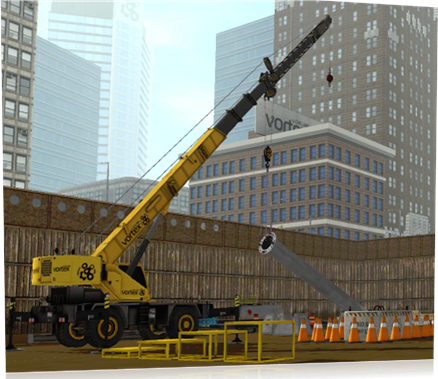
Cable Systems Module
Vortex Studio’s Cable Systems provides a realistic simulation of heavy-equipment cables. These extended capabilities ensure real-time behavior by allowing cables to adjust to bends while distributing mass and forces correctly. Additionally, Cable Systems includes simulation of winches and pulleys, and simulates cables’ interaction and collision with other dynamic Vortex Studio objects, or with themselves.
- Simulate objects such as wire, chains, and ropes for hoisting, towing, sling and other purposes for real-time simulations.
- Set cable way points using winch, pulley, attachment point, and ring.
- Optimize performance by defining which segments are flexible.
- Define resistance to cable deformation while stretching, bending, and applying torsion.
- Set cable stiffness using parameters that are independent of the cable’s resolution o Parameterize cable using Young’s modulus, relative elongation and number of wires
- Simulate extra-long cables with a minimum number of segments — the number of segments changes depending on the curvature of the cable using Adaptive Cable method.
- Employ spooling using a lock velocity or a motorized control for simulating different types of spooling behavior.
- Spool cable in and out of a fixed point.
- Break cables at a pre-defined location when the tension is exceeded.
- Cut cables at a specific location using the Cable Cutter extension.
- Lock a part to any desired flexible cable segment at its current location with a Cable Grabber extension, and use it to apply forces on the cable. o Measure cable tension on either side of the grab
- Assign contact materials and make a cable collide with its environment.
- Set the cable to interact with a specified fluid and establish the cable’s buoyancy.
- Add / remove Cable during runtime simulation.
- Activate / deactivate Cable during runtime simulation.
- Beyond generic cable, more specialized types are available:
- Catenary cables: ideal to model risers (U Shape, Steep Wave, and Lazy Wave) and freehanging cables (mooring line, umbilical, etc.). They are animated with collision geometries and are not dynamically impacted by contact from other entities. o Pipelines: user-defined cable paths, such as flow-lines, that are static with collision geometries. Pipelines are not dynamically impacted by contact from other entities.
- Activate the Geometric Stiffness feature to stabilize cable simulation under strong loads without adding unwanted and unrealistic damping effects.
- Trade collision accuracy for speed with the Low Precision Contacts option.
- Mesh Spline option automatically instances 3D geometries along its length.
- Quick modeling of items like tank and excavator tracks, chains o Display parameters such as distances between links can be controlled
- Snapback models whiplash effect occurring when cables or hooks break under tension.
- Effect can be added to both Generic Cables and Hook Groups o Parameters available to control both direction and energy
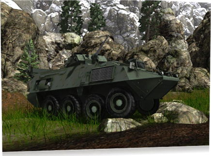
Vehicle Systems Module
Vortex Studio’s Vehicle Systems is a module that provides additional vehicle simulation services and utilities for both tracked and wheeled vehicles. These extended capabilities include engine, transmission, suspension, and steering simulation components. Additionally, the interaction between soil and tires or tracks can be parameterized to account for varying traction performance on different soils like mud, sand, or asphalt.
- Create highly realistic wheeled and tracked vehicles based on engineering design parameters.
- Select vehicles from a list of predefined templates including standard car, truck, trailers, and construction equipment models, or edit the templates to suit your specific needs.
- Build complete driver simulations by integrating vehicle controls directly on a Vortex Studio vehicle.
- Simulate complete vehicle dynamics: interaction between chassis, wheels, suspension, power train, and any other component.
- Set the vehicle’s axles and create its chassis, including defining its mass and center of mass
- Set wheels’ dimensions, mass and inertia for wheeled vehicles
- Set road wheels, sprocket and idler location, dimensions, and mass for tracked vehicles
- Access all vehicle mechanical properties for power train, such as engine, torque converter, transmission and differential.
- Set the maximum torque used when engaging a vehicle’s differential locks.
- Tune the engine using a full, adapted, or scalable torque table. The torque table describes the amount of torque the engine can deliver at a set RPM and for a given amount of throttle.
- Insert external CSV files containing Lambda and Ctr torque tables. Define the transmission’s gear ratios and final gear ratio Program automatic gear changes based on RPM.
- Restrict which gears are available during a simulation.
- Specify simple or quick gear-shifting modes.
- Define a transition time between an automatic transmission’s gears.
- Define suspension for wheeled or tracked vehicles, including stiffness, damping behavior, and maximum travel.
- Suspension displacement is available as an output
- Define steering model (Ackerman 2 or 4 wheels, crab, pivot, or custom).
- Define braking controls and logic.
- Input shaft velocity from external source and output resulting torque on vehicle systems’ components.
- Insert tire models to define the interaction forces applied at the tire/ground interface.
- Soft terrain and hard ground supported, based on semi-empirical models.
- Hard ground: Pacejka 1997 and 2002 Magic Formula, Composite Slip, Fiala, and standard contact (Coulomb)
- Soft terrain: Bekker, Wong, Reece, Muskek, and Snow Tire pressure can be used to determine stiffness.
- Soft ground tire models capture rolling resistance from ground deflection.
- Tire Model can be added to vehicles from previous Vortex Studio releases.
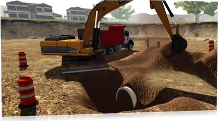
Earthwork Systems Module
Vortex Studio’s Earthwork Systems is a module that allows you to easily add earthmoving capabilities to a simulation. It provides a toolset similar to that found in industry-standard earthmoving equipment, along with the ability to define zone of terrains where tools can interact with soil materials in various ways (compression, cutting, piling, dumping, shearing, etc.). Earthwork Systems comes with several predefined standard soil materials such as clay, sand, loam, and gravel.
- Simulate highly deformable, plastic objects, using volume representation for the several modes of soil that must be represented: o Static soil in its ground state or in stable piles o Soil that is pouring or settling o Soil that is being compressed or sheared or separated through interaction with a tool
- Simulate soil-like materials emitted from artificial sources, such as hopper or concrete pump.
- Deformable three-dimensional geometric representation, which allows fast deformations, calculations of excavated volume.
- Hybrid particle-surface model to allow different geometric representations and different force models.
- Simulate deformation and compaction due to vehicle wheels and tracks on vast surfaces with improved performances.
- Provide realistic piling behavior of wet soils such as loam or clay via cohesive soil model.
- Support soil deformation physics such as compaction, soil separation, erosion, and soil flow.
- Position dump and dig zones across terrain surface.
- Set the shear strength of soil.
- Control the maximum number of soil particles as well as culling rules in scenes.
- Library of user-configurable tool-soil interaction tools.
- Standard deformation tools include excavator bucket, generic bucket and blade o Soil bin for truck bed and cargo hold-like equipment, with ability to start the simulation with an initial soil load o Soil Emitter available to generate soil particles
- Soil Culling Geometry and Monitor remove soil particles on touch, and monitor the culled particle mass
- Soil Layer allows for adding layers of soil to Earthwork Zones and Soil Bins, can be used to bury objects in ground
- Grade Quality sensor can compare the shape of terrain in a given box to a plane o Support soil accumulation, flow around borders, and pouring out using particles o Includes sand, loam, clay, and gravel soil material types
- Have several digging tools of different sizes operating within the same scene and on the same earthwork zone.
- Enable or disable earthworks tools at runtime.
- Add specialized material modifiers to the Earthwork graphics.
- Erosion flow to simulate collapsing soil on slopes o Tri-planar texture mapping to prevent undesired texture stretching on slopes o "Height Colorization," when set with a transparent texture, to colorize the earthwork zone and provide visual feedback about current depth to the operator
- Render a soil material between particles with Screen Space Mesh (SSM) to create a smooth and consistent look for visually chaotic soil while keeping computations to a minimum.
- Set multiple Graphic Materials in Soil Clump meshes o Set blur and noise effects to tune appearance o Control soil/rock visual ratio
Hydraulic Systems Module
Vortex Studio’s Hydraulic Systems is a module that allows you to easily add real-time hydraulic systems to a machine or vehicle without requiring Python scripting or co-simulation with an external, dedicated hydraulics simulation. It provides pre-packaged objects that can be inter-connected with each other or with other simulation objects, such as shafts or control scripts. Some common hydraulic components like relief valves, fluid reservoirs and lines are abstracted; others, like control valves, are directly included into the provided hydraulic objects, along with their operating parameters.
Note: the 2020a version is only a technical preview and not the final version of the feature. User feedback is welcome!
- Build real-time hydraulic systems for machines or vehicles without Python scripting or cosimulation with an external hydraulics simulation.
- Model hydraulic components such as transmission, pump, actuator, and manifold (both divider and combiner types).
- Connect hydraulic components to each other or to simulation objects such as engines, shafts, control scripts, etc.
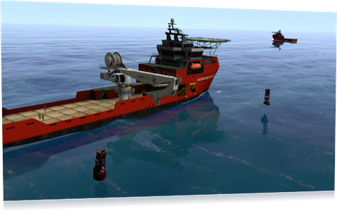
Vortex Marine
Vortex Studio’s Marine add-on provides fluid simulation of buoyancy, drag, and added mass hydrodynamic effects on rigid bodies when interacting with large bodies of water for amphibious and underwater vehicles. Vortex Marine includes Sundog Triton for a stunning water rendering effect.
- Fluid interaction supporting buoyancy, drag, and lift.
- Set detailed parameters for each part o Displaced Volume o Drag Coefficient o Lift Coefficient o Kirchhoff tensor o Added Mass
- Customize water density for more accurate buoyancy
- Full JONSWAP, Tessendorf and Pierson-Moskowitz wave spectral models.
- Quickly define sea state using Beaufort or Douglas scale number.
- Customize sea state by adding wind fetches and swells to produce wave heights and motion consistent with any wind speed and direction.
- Further customize sea state by adding wave components to model more complex wave systems, albeit at a cost to performance.
- Langmuir circulation visual effect automatically added based on wind speed and direction.
- Attach object to ocean heave for animating items that do not require full dynamics simulation, such as buoys or markers.
- Measure height from the waves for any object.
- Simulate thrusters by applying directional force based on propeller’s RPM.
- Realistic 3D water and ocean rendering.
- Customizable underwater silt particles (color, density, shape, etc.) o Underwater visibility control o Object, environment and light reflections on ocean surface o Particle spray on bow wakes and breaking waves o Fully customizable propellers wash effect on ocean’s surface o Fully customizable wake effect on ocean’s surface o Basic Kelvin wake effects with fully exposed parameters o Customizable wave heights with fully exposed parameters o Apply textures on ocean’s surface and control properties for special effects such as water impacts and wind shears
- Control specular reflection on ocean to dampen or disable reflection of a light source