Using QtDesigner Page
- DEVOPS
What is the QtDesigner Page?
QtDesigner Page provides the base for creating a user interface page that connects to the simulation. Such user interfaces are necessary to allow user interaction with the simulation; for a particular device or machine, like clicking a button to start the engine, or for manipulating the scene setup, like dragging a slider to change a weather setting. The Qt pages in the user interface comprise an interactive UI that adds an additional layer of realism to the simulation and allows users to interact with and receive feedback from the simulation.
For an overview of how a page created with QtDesigner Page is managed in the simulation refer to Adding UI Pages.
QtDesigner Page is added as part of the simulation content and is a role feature that can be added to a specific role in the simulation.
Usage of QtDesigner Page
There are several steps involved in the setup and configuration of an interactive UI that can be summarized as follows:
- Create a Qt UI file and populate it with Vortex custom widgets
- Add QtDesigner Page to the simulation content and populate input and output fields from the UI file
- Connect page fields for controls to the simulation content
- Configure windows for displaying the UI in the interface
The steps are detailed in the following sections.
Creation of Qt UI file
Vortex Studio comes with the Qt application designer.exe that is used to construct a UI file that will be used by a QtDesigner Page. Refer to Qt Designer Manual for more details about the UI file.
All standard Qt widgets can be used in a UI file. Several additional widgets are available for use with Vortex Studio, which are particularly well suited to creating a simulated equipment HMI.
For the following example, an existing UI file of the Demo Scenes is used. Make sure you have the proper Vortex Demo Scenes version installed.
Run designer.exe from the Vortex installed bin directory
At start, Click Open..., then browse to open
[drive:]\CM Labs\[Vortex Studio Content version]\Demo Scenes\Equipment\Excavator\UI\OperatorPage.ui
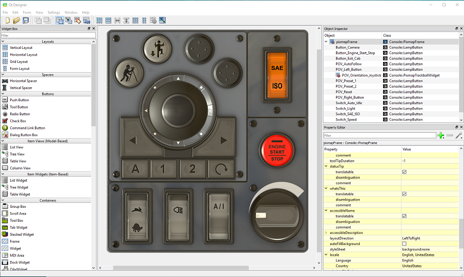
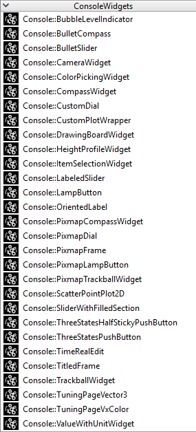
- In the Widget Box pane, all the default widgets listed come from Qt. In addition, you will also find a list of Vortex custom widgets with the Vortex icon under the category ConsoleWidgets. Refer to Vortex custom widgets for more details of each widget.
- Drag and drop desired widgets depending on your use case onto the create form widget. For this example, drag and drop a progress bar Console::SliderWithFilledSection.
- In the Property Editor pane, along with default properties by Qt, you will find the custom properties with default values under the Console categories. You can change them or leave them as defaults depending on your needs. In this, make changes as shown in the below image.
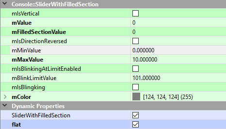
Note that not all widgets provide interactive capabilities, some are created just for visual feedback of the simulation. In the progress bar case, the widget does not take mouse or keyboard inputs from the user. It is meant for displaying property status from the simulation. For instance, the added progress bar in this example is used for reporting the machine's engine speed.
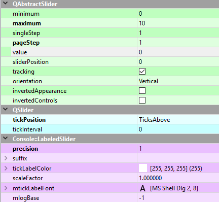
- One example of the widget with interactive capability is Console::LabeledSlider. The user can move the slider handle to specify a single value within a specified range. In this example, the slider is used for adjusting the engine speed. Drag and drop the slider widget and change the parameter value as shown
- Additional custom widgets can be added to the form depending on the use case. Note that QtDesigner Page is designed to work with Vortex custom widgets that allow interactions with the simulation.
Note: If any default widget by Qt is used and added to the form, it is meant for additional presentation on the page. The user will not be able to use it for interaction with the simulation.
- Save the UI file.
Creation of QtDesigner Page
Once the UI file is prepared for a specific mechanism, the next step is to modify the QtDesigner Page in the mechanism using Vortex Editor. This step allows the user to configure the user interface for the simulation.
Modify the QtDesigner Page in the content
- Run Vortex editor and open the excavator mechanism:
[drive:]\CM Labs\[Vortex Studio Content version]\Demo Scenes\Equipment\Excavator\Dynamic\Design\Excavator.vxmechanism
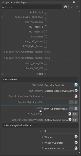
- Expand the HMI folder in the explorer tree and select HMI Page. In the property browser on the right side of the Vortex Editor, scroll down the list until the UI File property is visible
Note:
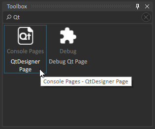
If a new QtDesigner Page is required to be added to the content, add it from the Toolbox. In the search box, type 'Qt' so the QtDesigner Page item is shown. Double-click the item or drag & drop it onto the desired folder in the explorer tree.
Initially, in the property browser of the added page extension, you will find empty parameter fields as shown in the table. There are no input or output fields. Refer to Adding UI Pages for more details of each parameter and its description.
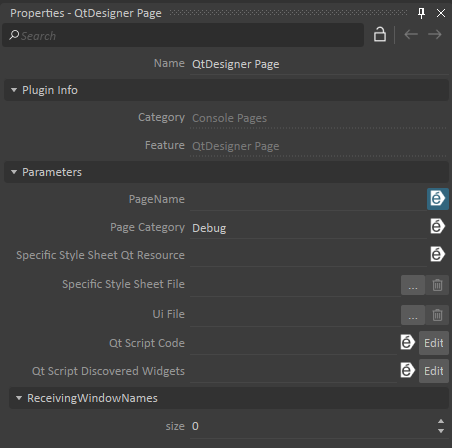
- Select the Console tab at the bottom of the Vortex Editor

Note: the widgets in the UI file are shown in the Console tab, but without the progress bar and slider widgets that were added in the previous step with designer.exe. The reason is that loading the mechanism in the Vortex Editor does not automatically load the updated UI file. You need to load it manually.
- Click the three-dot button in the UI file property editor, and browse for the UI file. Once the selected UI file is applied, input or/and output fields for the newly added progress bar and the slider widgets are automatically populated for the QtDesigner Page. The Console tab now shows the newly added widgets
Note: QtDesigner Page is populated with the new fields as shown in the property browser for the newly added widgets. The number of input fields may not be the same as the number of output fields. For example,
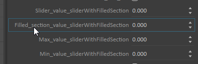
SliderWithFilledSection widget: 5 input fields, there is no output field. In this case, the widget does not take mouse or keyboard inputs. It is meant for displaying property status from the simulation. For instance, it is used for reporting the machine's engine speed.
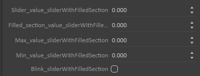
LabeledSlider widget: 1 input field and 1 output field. In this case, the widget takes mouse or keyboard inputs and can also be used for displaying property status.
![]()
- Changing the slider handle position will update the output field labeledSlider.
Note: This is possible because there is a connection from the slider widget and its associated output field labeledSlider. However, at this point, there are no connections between the widget and the mechanism's properties. The next section will guide you through the creation of connections.
Connections between the widgets and the content's properties
In order to demonstrate how the widgets work with the content's properties, the existing script will be modified.
In the explorer tree, expand the HMI folder.
- Right-click the Excavator PLC object and select Edit
- Click the Add button in the Output category to create a new output field
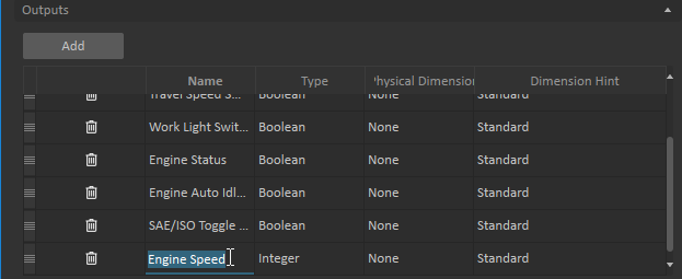
- Change the new field's Name to Engine Speed and Type to Integer.
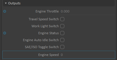
- Click the OK button to apply. The new output field Engine Speed is added to the property browser.
On the Script Path field, click the three-dot button to browser for the Excavator PLC.py. Use a text editor to edit the script, and add the new line outlined in green below:

- In the HMI folder, double-click on the HMI Connections object to edit the connections
- In the HMI folder, select the HMI Page object. From the property browser, drag the output labeledSlider onto the Excavator PLC's input Engine Speed Dial in the connection editor to create a connection between them.
Note: once the connection is made, there should be a blue circle displayed next to the field in the property browser.
- Enter 10 for the input Max_value_sliderWithFilledSection
- Drag the input Filled_section_value_sliderWithFilledSection onto the connection editor
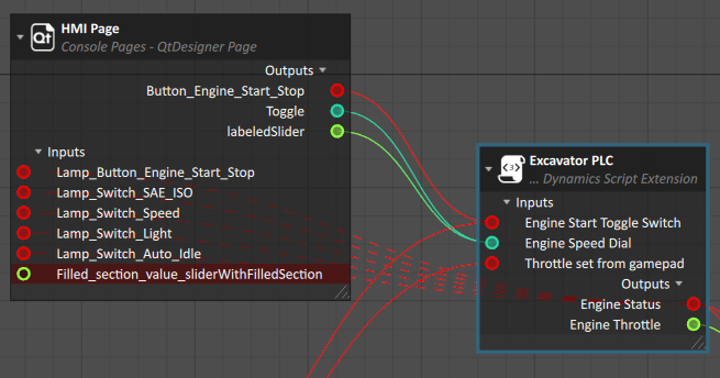
- In the HMI folder, select the Excavator PLC object and drag its output Engine Speed onto the input Filled_section_value_sliderWithFilledSection to connect.
- Click the Start Simulation button and move the slider handle to interact with the simulation.
Moving the slider up and down, the Script's input Engine Speed Dial and output Engine Speed are updated. Also, the progress bar on the HMI page is updated.
Show the interactive UI in Console
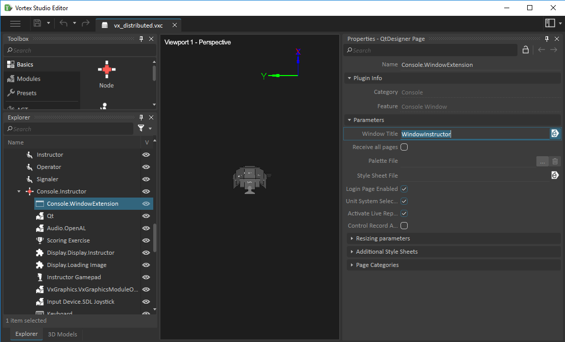
- QtDesigner Page has a parameter ReceivingWindowNames. The parameter is used to specify the name of each window in the console that displays the page. The following shows the UI will be displayed in two windows of two separate nodes:
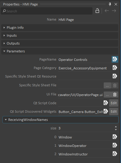
- The window's name can be found in the Console Window extension of the specific node in the setup file .vxc.
Vortex custom widgets
Vortex Studio comes with a list of Vortex custom widgets that can be added to the .ui file for creating UI in Vortex Console. For a complete list of widgets with descriptions, refer to Specialized Widgets for UI pages.