Manipulating Objects in the 3D View
- DEVOPS
Analytics
Transform toolbar
You must first select an object before you can use the buttons in the Transform toolbar as shown below.

Transform Object:
1: Move 2: Rotate 3: Resize 4: Measure
Transform Object's Mass Properties:
5: Move 6: Rotate 7: Resize
Tool feedback
8: Transform Feedback
Snap Object:
10: Snap to Grid 11: Snap to Surface 12: Snap to Angle
Transform settings:
9: Local and World reference.
13: Resize Type
14: Grid Settings
Context Display
Conventions
Depending on objects that are selected in the 3D view or the Explorer view, buttons to manipulate the selected objects are enabled ![]() or disabled
or disabled ![]() accordingly.
accordingly.
In most case, the selected active button has a light blue background ![]() , others simply have a black background.
, others simply have a black background.
In some cases, blue and black button backgrounds are also used to differentiate between the toggle options such as the Local/World Reference ![]()
![]() or the Resize Type button
or the Resize Type button ![]()
![]() .
.
Clicking the Move, Rotate, Resize and Measure buttons, the transform feedback ![]() will show the proper transform information.
will show the proper transform information.
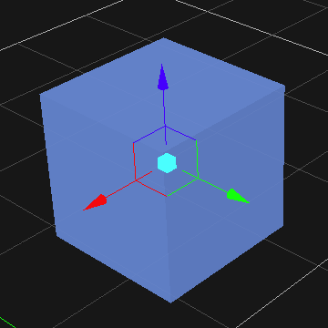
When manipulating objects in the 3D View, an axis will be displayed to indicate that the object can be manipulated. This axis may be different depending on the action, such as rotating, moving or resizing.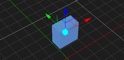
Tip
To help you identify objects more quickly, you can view collision geometries in color.
To show collision geometries in color, from the Editor home page, navigate to the Options menu → Display tab →Collision Geometries and then click to select Enable Color Display.
Transform Object:
Transforming objects can be done in local or world reference. For more details, refer to Local and World reference
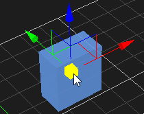
Moving an Object
- Select the object in the 3D View or the explorer view. The object's color is changed to indicate that it is selected.
- From the Transform toolbar, select the Move button
 . The axis is displayed on the object.
 - Do one of the following:
- Click the X, Y, or Z axis and move the object along the axis.
- Click the plane in between any two axes to move the object along two axes at once. Note that the color of the plane matches the axis that will be ignored.
- Click the box at the origin of the axes to move the object on all planes.
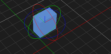
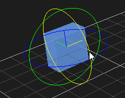
Rotating an Object
- Select the object in the 3D View or the explorer view. The object's color is changed to indicate that it is selected.
- From the Transform toolbar, select the Rotate button
 . The rotate controls and the center axis are displayed on the object.
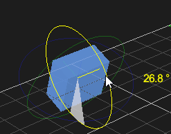
 - Select the axis that appears yellow while selected and rotate the object around it. While rotating, the angle value is shown in degrees.
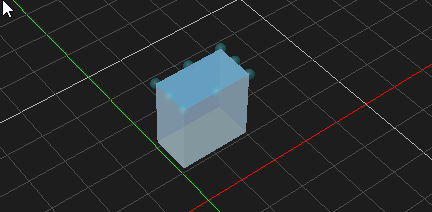
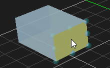
Resizing an Object
Objects that are resizable include collision geometries (box, sphere, cylinder and capsule), decal object and deformable terrain object. The button becomes enabled when resizable object is selected.
- Select the object in the 3D View or the explorer view. The object's color is changed to indicate that it is selected.
- From the Transform toolbar, select the Resize button
 .
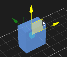
. - Select the area in the object that you want to resize:
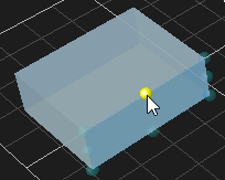
For box, click one of the faces and drag to resize. Resize type can be chosen to resize symmetrically or just resize one side. For more details, refer to Resize Type
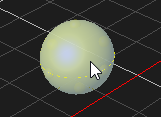
For spheres, click the sphere surface and drag to resize along the diameter.
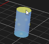
For cylinders and capsules, you can resize the diameter and the height.
4. Select one of the resize handle and pull it along one axis or diagonally if you want to resize in two axes at once.
Measuring an Object
You can use the Measure tool to find the distance between two objects, or two points on the same object.
- Select the Measure button
 in the Transform toolbar to activate the measuring function.
 - Click an object to start measuring
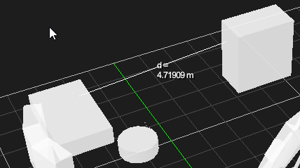
- Move the cursor to the point whose distance you want to measure from the initial position. The measuring line will change from red to white when you hover over an eligible object.
- Click once you have settled on an eligible object.
A line now appears, displaying the distance (in meters) between the two selected points.
The measurement feedback in the toolbar ![]() shows a difference in position between the two points along the three axes.
shows a difference in position between the two points along the three axes.
Transform Object's Mass Properties
The Mass Properties tools ![]() are used for editing a part's center of mass (COM) and inertia tensor which are essential for accurate and stable simulations. The users can also modify the COM and inertia via the Properties panel. For more details about COM and Inertia, refer to Parts section Editing the Part's Mass Properties.
are used for editing a part's center of mass (COM) and inertia tensor which are essential for accurate and stable simulations. The users can also modify the COM and inertia via the Properties panel. For more details about COM and Inertia, refer to Parts section Editing the Part's Mass Properties.
Part's COM and inertia tensor are modifiable in Assembly document in which parts are created. Transforming COM and Inertia can be done in local or world reference. For more details, refer to Local and World reference
The Mass Properties tools are enabled if any part is selected and the Move or Rotate tool is selected in the Transform toolbar.
The graphics for the center of mass is simply a sphere  and for the inertia tensor is an ellipsoid
The graphics for the center of mass (COM) and the inertia tensor are not visible by default. To show the graphics, in the explorer view, right-click on the eye icon of a part and check on the menu Center Of Mass and Inertia. 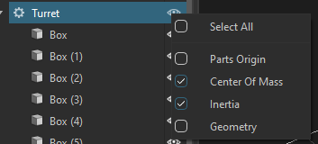
If the COM and Inertia graphics are still not shown, it means the main Debug Display tools are not enabled. For more details about the Debug Display tools, refer to Using the Debug Display Tools
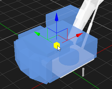
Move COM
- Select a part in the 3D View or the explorer view.
- From the Transform toolbar, select the Move COM button
 . The axis is displayed on the object.
 - Do one of the following:
- Click the X, Y, or Z axis and move the COM along the axis.
- Click the plane in between any two axes to move the COM along two axes at once. Note that the color of the plane matches the axis that will be ignored.
- Click the box at the origin of the axes to move the COM on all planes.
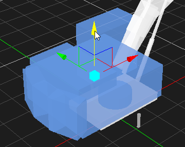
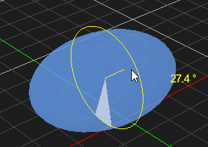
Rotate Inertia
- Select a part in the 3D View or the explorer view.
- From the Transform toolbar, select the Rotate Inertia button
 . The rotate controls and the center axis are displayed on the ellipsoid.
 - Select the axis that appears yellow while selected and rotate the object around it. While rotating, the angle value is shown in degrees.
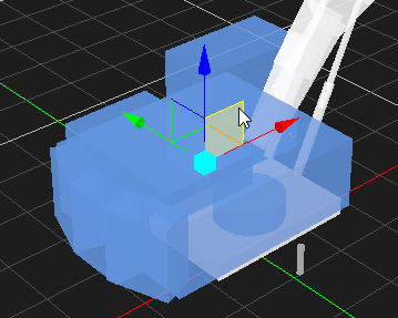
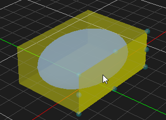
Resize Inertia
- Select a part in the 3D View or the explorer view.
- From the Transform toolbar, select the Resize Inertia button
 . A box is shown and encloses the inertia ellipsoid graphics.
 - Click one of the faces and drag to resize. Resize type can be chosen to resize symmetrically or just resize one side. For more details, refer to Resize Type
Snap Object
Snap to Grid
The Snap to Grid button ![]() is enabled when the Move tool is selected.
is enabled when the Move tool is selected.
When the Snap to Grid button is selected ![]() , objects move in horizontal and vertical increments as defined in the Grid Options.
, objects move in horizontal and vertical increments as defined in the Grid Options.
If you move an object away from the grid, press the drop-down arrow of the Snap to Grid button, then Snap to Closest Grid Point. The object will automatically move to the closest grid point.
Snap to Surface
The Snap to Surface button ![]() is enabled when the Move tool is selected.
is enabled when the Move tool is selected.
Enabling the Snap to Surface button ![]() allows you to quickly align objects with surfaces.
allows you to quickly align objects with surfaces.
To use Snap to Surface:
- Select the object to be snapped.
- Click the Move transform button.
- Click the Snap to Surface button to activate the feature.
- Click the drop-down arrow in the Snap to Surface button.
- Select Follow Surface Normal if you want the object to orient itself with the plane of the other object's surface.
- In the Axis to Align field, select the directional axis of the object that you want to snap to another object. Use the axes indicators to help you determine the orientation of your object:
- Red points in the +X direction
- Green points in the +Y direction
- Blue points in the +Z direction
Select an Offset (in meters) if necessary.
By default, the center of the object will snap to another object's surface. In some instances, e.g., stacking boxes, you would have to set an offset to have the surface of one object snap to another.- Click and drag on the point of origin at the center of the axes to move the object close to the target object to snap them together.
Optionally, there is also a Snap to Floor button in the drop-down menu to snap the selected object to the default floor of the 3D View space.
Snap to Angle
The Snap to Angle button ![]() is enabled when the Rotate tool is selected.
is enabled when the Rotate tool is selected.
While you can enter an object's rotation directly in the object's Properties panel, enabling the Snap to Angle button ![]() allows you to rotate an object in a more controlled way.
allows you to rotate an object in a more controlled way.
To use Snap to Angle:
- Select the object to be snapped.
- Click the Rotate transform button.
- Click the Snap to Angle button to activate the feature.
- Click the drop-down arrow in the Snap to Angle button.
- Specify the increment (in degrees) that you want the object to rotate.
When you rotate the object with this feature enabled, the object will turn in the increment that you specified.
Transform settings:
Local and World reference
Transforming objects, part's COM and inertia can be done in local or world reference. When local reference is active, transforming an object happens with respect to the object's own coordinate system. When world reference is active, transforming an object happens with respect to the world coordinate system. For more information about the object's transform properties, refer to Transforming Objects
The Local/World Reference button ![]() is enabled when the Move, Rotate, Move COM or Rotate Inertia tool is selected.
is enabled when the Move, Rotate, Move COM or Rotate Inertia tool is selected.
Clicking Local/World Reference button toggle between Local reference ![]() and World reference
and World reference ![]()
Resize Type
The button is enabled if the Resize tool is selected. There are two types of resize, one-side resize and symmetrical resize. By default, one-side resize is activated. Click the button ![]() to toggle between types.
to toggle between types.
- One-side resize
 is used to resize one side of the object.
 - symmetrical resize
 is used to resize both sides of the object with the anchor point as the center of mass of the resizing object.
Grid Settings
The position and orientation of the grid display can be controlled via the Grid Settings button ![]() . For more detail about the grid options, refer to Grid Options.
. For more detail about the grid options, refer to Grid Options.
Click the Grid Settings button to toggle on or off the grid graphics display.
Click the dropdown button to edit the grid's position and orientation.
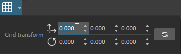
To reset the grid transformation to the default, click the button ![]()