Getting Started Tutorial 3 : Creating a Mechanism
In this tutorial, you will learn the basics of Vortex® Studio Editor by importing graphical assets that are created by 3D artists and turning them into a simulated vehicle. These graphical assets must be created using the Vortex 3D modeling guidelines to be divided into logical parts based on their expected mechanical behavior.
Using the graphical asset provided, you will simulate a simplified forklift mechanism with moving parts and constraints using common Vortex building blocks. You can further enhance the simulation by connecting an input device and using a script to modify the functionality. We will cover this in the following tutorial module.
Prerequisites
You need to have Vortex® Studio and the Vortex Studio Demo Scenes installed to be able to follow all steps in this tutorial.
Import Graphical Assets
In this step, we will import an existing 3D model into the Vortex Studio Editor and prepare the file for work by adding an assembly to receive the various parts and constraints. Generally, a 3D artist creates a Graphics Gallery from existing 3D models but for this tutorial, a Graphics Gallery is already provided. The default location is C:\CM Labs\Vortex Studio Content<version>\Demo Scenes\Equipment\Forklift\Graphic where <version> is the currently installed version.
- Create a new mechanism file.
- Rename the mechanism to "Forklift" by selecting the new mechanism in the Explorer panel, then either:
- Press F2 for editing mode, edit the name, and press Enter to confirm.
- Click within the Name field at top of the Properties panel to change the name in the dialog box.
- Select Graphics in the Toolbox. Double-click Galleries From Files...
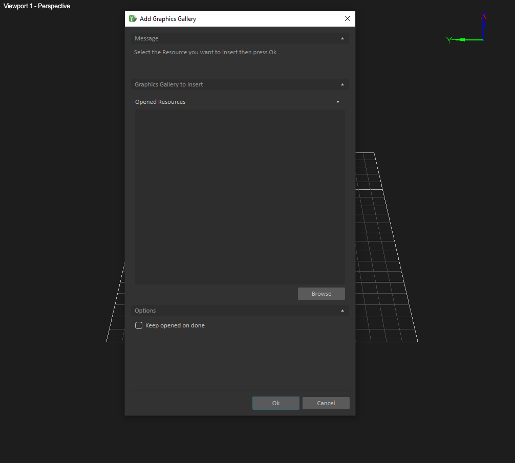
In the resulting Add Graphics Gallery panel, locate
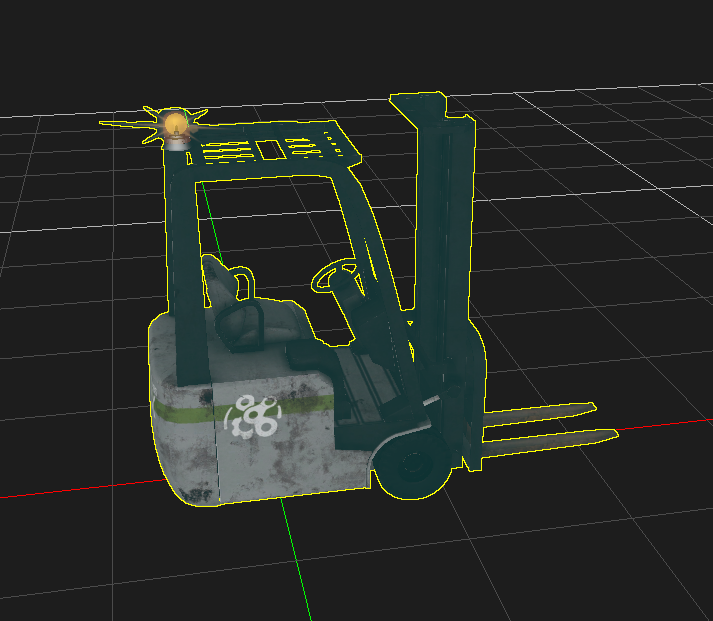
ForkLift.vxgraphicgallery, then click Ok.You should now see the forklift model in the center of the viewport. In the Explorer panel, the 3D model is located within a folder that you can expand via the small triangle on the left. This Graphics Gallery contains the 3D model and its associated files (e.g., textures). You can see the various files but cannot interact with them. To do so, you must open the Graphics Gallery in a separate window. Leave this for now.
- Select Basics in the Toolbox. Double-click Empty Assembly. The assembly is a container for the dynamics objects (parts and constraints) that will be added next.
- Save the forklift file.
Create Parts for Front Wheels
In this section, we will use the various graphic nodes of the model as starting points to create parts.
- Select the forklift Graphics Gallery in the Explorer Panel. Using the small triangles on the left, expand the hierarchy and you will find the following graphics nodes: Wheel Front Left, and Wheel Front Right.
- Right-click on the graphics node of the left wheel and select Create Part in... This will create an Assembly.
- Right-click on the graphics node of the right wheel and select Create Part in Assembly.
Press the Start Simulation button on the Toolbar (or press F7). The wheels will fall through the grid. Parts need to have collision geometry to interact with the environment.
Once a graphics node is assigned to a part, it no longer moves with its parent node.
- Right-click on each wheel part in the assembly and select Create Best-Fit Geometry > Best-Fit.
- Test the mechanism again and see that wheels no longer fall through the grid.
Assign Materials
In this step, we will add a material table to define the contact properties of the various materials assigned to the parts, and change the properties of the grid so that we can use it for testing.
- Click the Panel Selection drop-down at the top-right corner of the Vortex Studio Editor window, and select Material Table.
- Next, assign a material to the grid by right-clicking in the 3D Viewport and selecting Grid... In the Material field, select Ground from the drop-down list.
The material assigned to the grid is not saved and will have to be reapplied if the Editor is restarted.
Assign Mass and Inertia Properties to Front Wheels
In this step, we will assign mass and inertia properties to our newly-created parts. We will also assign a material to them.
- Right-click on the assembly in the Explorer panel and select Open Assembly... This opens the assembly file in a separate tab.
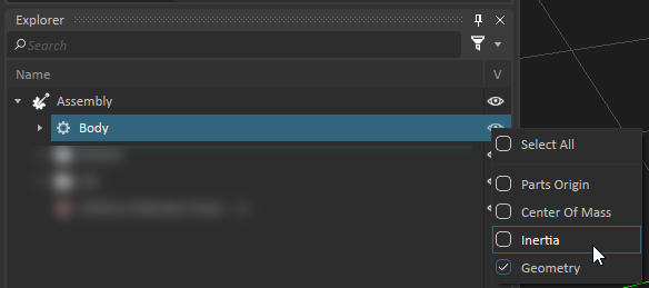
- In the Explorer panel, right-click on the eye
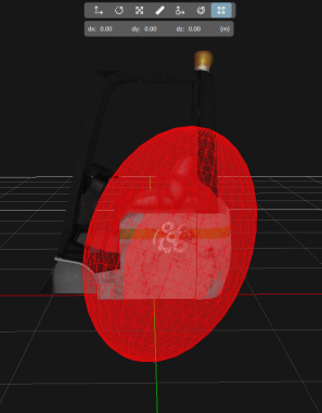
 icon next one of the Front Wheels part and select Inertia to make the inertia tensor visible. A sphere will appear around the wheel showing a visual representation of the body's current moment of inertia. This relates to how the mass is distributed in the part, and should generally match the size and shape of the part.
 - In the Parameters tab of the Properties panel, set the mass of the part to 30 kg.
- Click Compute Inertia and COM to automatically compute the moment of inertia of the part that most closely represents the shape of the collision geometries. Notice that the moment of inertia visualization now conforms more closely to the shape of the part.
- Assign a material by expanding the Part in the Explorer panel, selecting the collision geometry of the wheel (e.g., Cylinder_Wheel Front Left). Then, in the Material field of the Properties panel, assign the Wheel material by selecting Wheel from the drop-down list.
- Save and close the wheel part.
- Repeat steps 1-7 of this section on the other front wheel.
- Go back to the mechanism and test it using Mouse Spring (Alt+Click/Drag). While the wheels are still not connected to the rest of the forklift, their interaction with the ground is now more like rubber on pavement.
Create Additional Parts and Collision Rules
In this step, we will add parts to the rest of the forklift's components, give them material properties, and add collision rules so they do not interfere with each other.
- Under the forklift Graphics Gallery, create additional parts for the Rear Wheel Castor and Rear Wheels (expand Rear Wheel Castor to find it), using Create Part in Assembly.
Create best-fit collision geometry for Rear Wheels via Create Best-Fit Geometry > Best-Fit from the right-click menu of the parts.
- Create a part from the Body graphics node by right-clicking the Body part in the assembly and select Create Best-Fit Geometry > Convex Mesh. Then, press Ok to confirm.
Do not insert a collision geometry for Rear Wheel Castor. It is not needed since the part is largely covered by the body of the forklift.
- Open the Assembly.
- Set the material of the Cylinder_Rear Wheels collision geometry to Wheel.
- Set the material of the ConvexMesh_Body collision geometry to Chassis.
- Test the mechanism to see that the newly created parts break away from each other and move apart. They are still not constrained together.
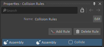
- Select Basics in the Toolbox, then double-click Collision Rules. In the Properties panel for the collision rules, press Add Rule.
- Drag and drop the Assembly in both fields of the rule. Do not check the Collide option. This will prevent collisions between all assembly components.
- Test to see the parts simply fall to the ground, but note that the wheels now pass through without interacting with the body. This is normal at this stage.
Assign Mass and Inertia Properties to Remaining Parts
In this step, we will assign mass and inertia properties to our newly created parts. We will also assign a material to them.
- Open the Assembly by double-clicking on it in the Explorer panel.
- Select the Rear Wheels part for the Explorer panel. Access the Parameters tab of its Properties and set the Mass to 60 kg.
- Press Compute Inertia and COM to set the inertia for the rear wheels.
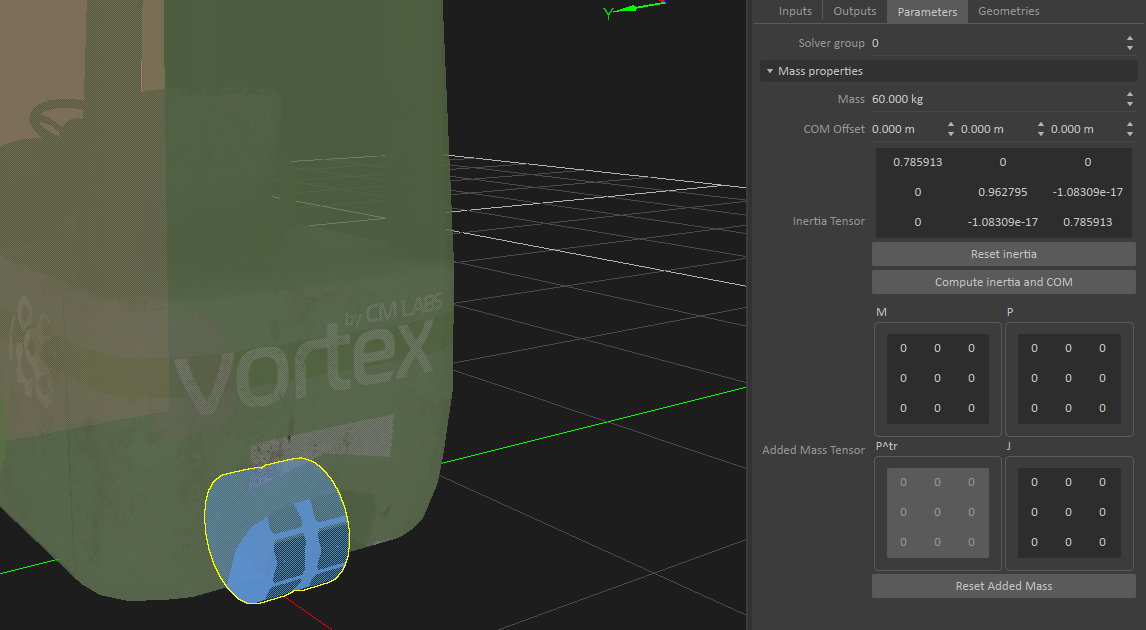
- Repeat for the Body part with a mass of 3000 kg.
- Adjust the body's inertia tensor. In the Explorer panel, right-click the eye icon next to the part, and select Inertia to make the inertia tensor visible, and deselect Geometry to hide the collision geometry.
Select Resize Inertia (Ctrl+8) from the Transform toolbar to modify its shape and position to reflect the fact that the engine section is heaviest.
Move/rotate/resize actions are easier to do on a 2D plane. Access the available views by right-clicking on the viewport. Press the 'P' key to get back to the perspective view.
Creating Constraints
In this step, we will add constraints to define how the various parts are attached together. Read up more on each constraint type available in Vortex here.
- Make sure you have the Assembly still open.
- Now we will add four Hinge constraints to the assembly (see the list immediately below these instructions for settings). Let's begin with the first row of the table. In the Toolbox, double click Common Constraints > Hinge.
- Select the newly-created hinge in the Explorer panel and edit the following fields in its Properties panel, according to the table below following these instructions:
- Name the constraint to make it easy to identify.
- Drag and drop parts from the Explorer to the Part fields.
- Indicate the position (if an offset is needed; none in this case).
Indicate primary and secondary axis by clicking on the Axis button at end of the line, then selecting the axis.
Constraint Name Type Part 1 Part 2 Position Primary Axis (Part 1) Secondary Axis (Part 1) Wheel Front Left [H] Body Hinge Wheel Front Left Body 0 m; 0 m; 0 m +Y: 0 m; 1 m; 0 m +X: 1 m; 0 m; 0 m Wheel Front Right [H] Body Hinge Wheel Front Right Body 0 m; 0 m; 0 m +Y: 0 m; 1 m; 0 m +X: 1 m; 0 m; 0 m Rear Wheel Castor [H] Body Hinge Rear Wheel Castor Body 0 m; 0 m; 0 m +Z: 0 m; 0 m; 1 m +Y: 0 m; 1 m; 0 m Rear Wheels [H] Rear Wheel Castor Hinge Rear Wheels Rear Wheel Castor 0 m; 0 m; 0 m +Y: 0 m; 1 m; 0 m +X: 1 m; 0 m; 0 m 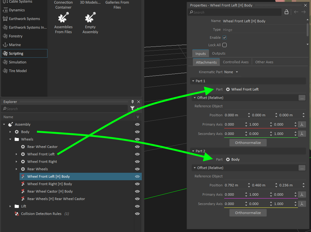

A Hinge is a two-part constraint, which allows control of the parts' relative rotation around the second part's primary attachment axis (the hinge axis). The corresponding controllable angular coordinate is called "Angular". The remaining five coordinates appear in the Other Axes tab and can optionally be relaxed. Read more here.
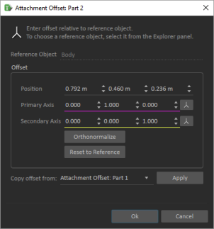
- Set the positions and axes of the constraint's "Part 2". Click the Browse button in the Offset (Relative) field of Part 2. In the resulting window, set the Copy From field to Attachment Offset: Part 1. Then, click Apply, then Ok.
- We will use a faster method, called multi-select, to create our second hinge. In the Explorer panel, select Wheel Front Right, then hold Ctrl and click Body. Both parts will now be selected. Now, while both parts are still selected, double-click Common Constraints > Hinge in the Toolbox. The hinge is created using those parts. Repeat steps 3 and 4 for this constraint.
- Similarly, create the hinges for the final two rows of the table above.
- Go back to the mechanism, begin the simulation, and test it using Mouse Spring to see how it behaves.