Getting Started Tutorial 2 : Creating your First Scene
This module focuses on the basics of using Vortex Studio to create a scene and launch a first simulation, as well as inserting mechanisms and interacting with them.
Prerequisites
You need to have Vortex® Studio and the Vortex Studio Demo Scenes installed to be able to follow all steps in this tutorial.
Creating a Scene
Start the Vortex Studio Editor.
Click on the Scene document type in the New Document section of the welcome screen to create a new scene.
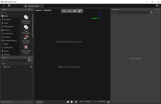
This will open the scene editor. By default, a new scene does not have any contents. This is why it displays messages indicating that you can drag Toolbox objects in the scene or right-click the workspace to configure scene options.
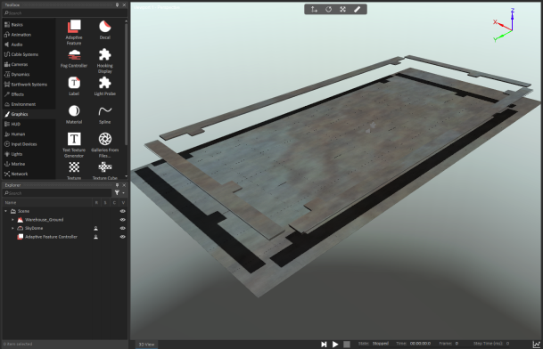
In the Environment section of the Toolbox, double-click on Terrain From File....
Click on the Browse of the Terrain File and find the Warehouse ground from your Demo Scenes folder (...\Vortex Studio Content <version>\Demo Scenes\Environment\Warehouse\Graphic\Warehouse_Ground.vxgraphicgallery).
Change the Default Material to Ground. Click OK.
In the Environment section of the Toolbox, double-click on SkyDome.
In the Graphics section of the Toolbox, double-click on Adaptive Feature.
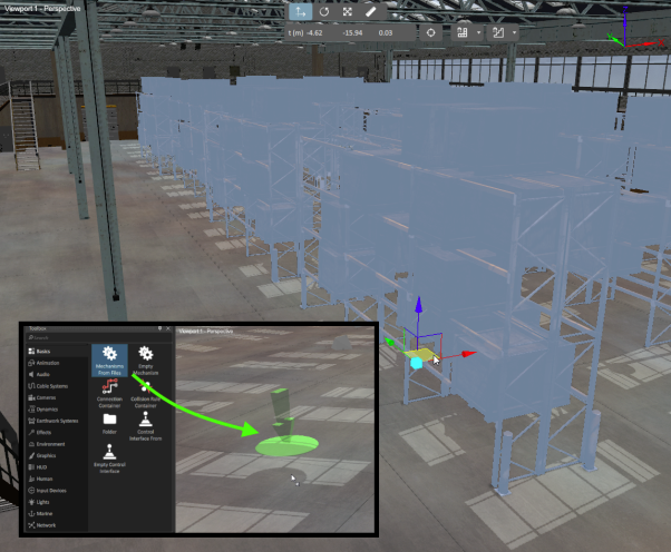
In the Basics section of the Toolbox, double-click on Mechanisms From Files. Click on Browse and find the Warehouse mechanism (...\Environment\Warehouse\Dynamic\Warehouse.vxmechanism).
By default, the ground and the warehouse should be aligned. If they are not, make sure that their Local Transform under Properties is set to the origin of the scene (0, 0, 0).
In the Basics section of the Toolbox, drag-and-drop a Mechanisms From Files on the ground. Click on Browse and find the Shelving_Units mechanism (...\Environment\Warehouse\Dynamic\Shelving_Units.vxmechanism).
Use the Move (Ctrl + 2) tool to position the shelves inside the warehouse.
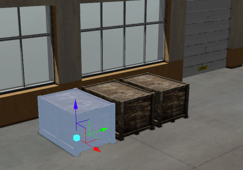
Repeat steps 9 and 10 for the Movable_Crate mechanism (...\Environment\Warehouse\Dynamic\Movable_Crate.vxmechanism).
Right-click on the Movable_Crate, Duplicate (Ctrl + D) it, and Move (Ctrl + 2) it side-to-side with the existing one. Repeat in order to have 3 crates side-to-side.
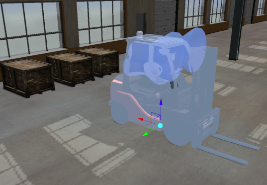
Repeat steps 9 and 10 for the Medium Forklift mechanism (...\Training\Forklift_Medium\Dynamic\Design\Forklift.vxmechanism).
Save (Ctrl + S) the scene in your working directory.
Set a Material Table
- Click on the three horizontal lines in the top left corner of the screen, and select Options. Then navigate to the Setup tab.
- Observe the material table set by default. This is a system-wide default and might not be appropriate for each specific project. Instead, the table should be defined in the assets.
- Close the Options and go back to the Scene.
- In the Simulation section of the Toolbox, add a Material Table to the scene.
- Click on Browse in the Material Table's Properties.
- Select the material table for the warehouse scene (...\Scenario\Forklift Scene\Forklift_in_warehouse_material.vxmaterials).
- The Material Table panel opens. This shows all defined material names, and the contact properties for each pair. Click on each combination of materials in the Material Table panel and observe the differences in the Properties panel.
Connect a Gamepad
- Make sure a Gamepad is plugged in. It can be tested in Windows from the "Set up USB Game Controllers" control panel.
In the Input Devices section of the Toolbox, add a Joystick to the scene.
The Joystick is not a graphical or mechanical object represented in the scene. It can only be found in the explorer and contains a set of inputs and outputs that communicate with the physical game controller.
- Observe which outputs of the Joystick object change when pressing buttons and moving the axes.
- In the Basics section of the Toolbox, add a Connection Container.
- Select the forklift's Control Interface VHL. Select all the input fields and drag-and-drop them into the Connections Workspace.
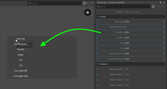
- Select the Joystick object. Select relevant output fields and drag-and-drop them into the Connection Workspace.
- Connect the inputs and outputs as shown in the image below.
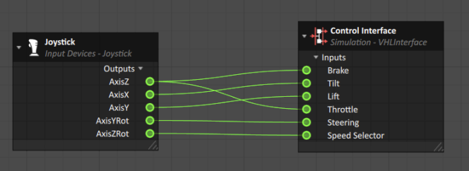
- Close the connection container (or change tabs) to return to the 3D View.
- Test (F7) the simulation and drive the forklift with the gamepad.
Adding a Head-Up-Display
- In the HUD section of the Toolbox, add three (3) Text objects.
- Open the Connection Container (double click, or change tabs if it's still open).
- Select the Text objects and drag-and-drop the "Text" input field from their Properties into the Connections Workspace.
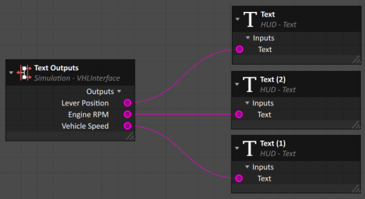
Select the forklift's Text Outputs interface. Drag-and-drop the output fields into the Connections Workspace.
The color of the connection ports are different depending on the data type. In this case, purple represents strings (text) and green represents doubles. The data types colors are documented here.
- Connect each Text object to an output from the Text Outputs interface.
Adjust the Anchor Position of each Text object to these values:
Text Value Anchor Position Lever Position [0.7, -0.90, 0] Engine RPM [0.7, -0.82, 0] Vehicle Speed [0.7, -0.74, 0] The Anchor Position is relative to the size of the screen and has a range of [-1:1] on the X and Y axis. The Screen Offset is a position relative to the Anchor and is measured by a number of pixels. For instance, an object with an Anchor Position of [-1, -1, 0] and an Screen Offset of [100, 80, 0] will be located on the bottom left of the screen with an offset of 100 pixels to the right, and an offset of 80 pixels to the top.
Test (F7) the simulation. Adjust the properties of the Text objects, like color and font size.
Save (Ctrl + S) the scene in your working directory.