Getting Started Tutorial 1 : The User Interface
In this tutorial, new users will learn the basics of interacting with Vortex® Studio Editor.
You will start from an existing Vortex Studio scene found in the Vortex Studio Demo Scenes installation directory. The default location is C:\CM Labs\Vortex Studio Content <version>\Demo Scenes\Scenario\Engineering Parkour/EngineeringParkour.vxscene where <version> is the currently installed version.
Prerequisites
You need to have Vortex® Studio and the Vortex Studio Demo Scenes installed to be able to follow all steps in this tutorial.
Tour of the Home Page
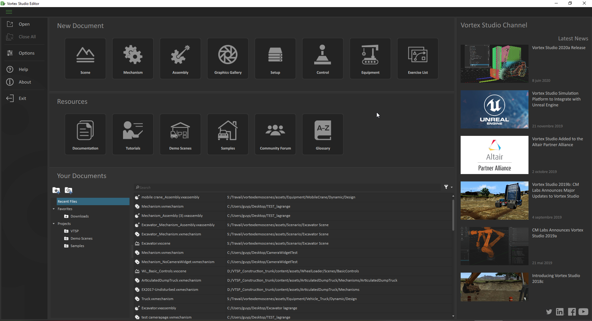
- Open the Vortex Studio Editor application. Once you launch Vortex Studio Editor, you will notice the window is divided into three sections:
- On the left: A column of application commands like Open, Options, and Help.
- Down the center: Buttons to create new file types, links to resources, as well as a list of recent files (and a filter for those files).
- On the right: Vortex Studio channel (providing you with links to company information).
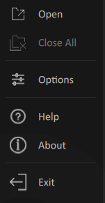
- Examine the application commands. The left-hand column contains the following useful commands:
- Open: Opens a window to select a file to open.
- Close All: Closes all open files.
- Options: Opens the Application and Add-ons Options panel to customize the display, simulation, and plug-ins, among other features.
- Help: Opens a web browser to the Vortex Studio Documentation. The documentation is also accessible by pressing F1 at any time.
- About: Provides you with software and legal information, as well as the license status.
- Exit: Closes the application. You will be prompted to save any unsaved changes.
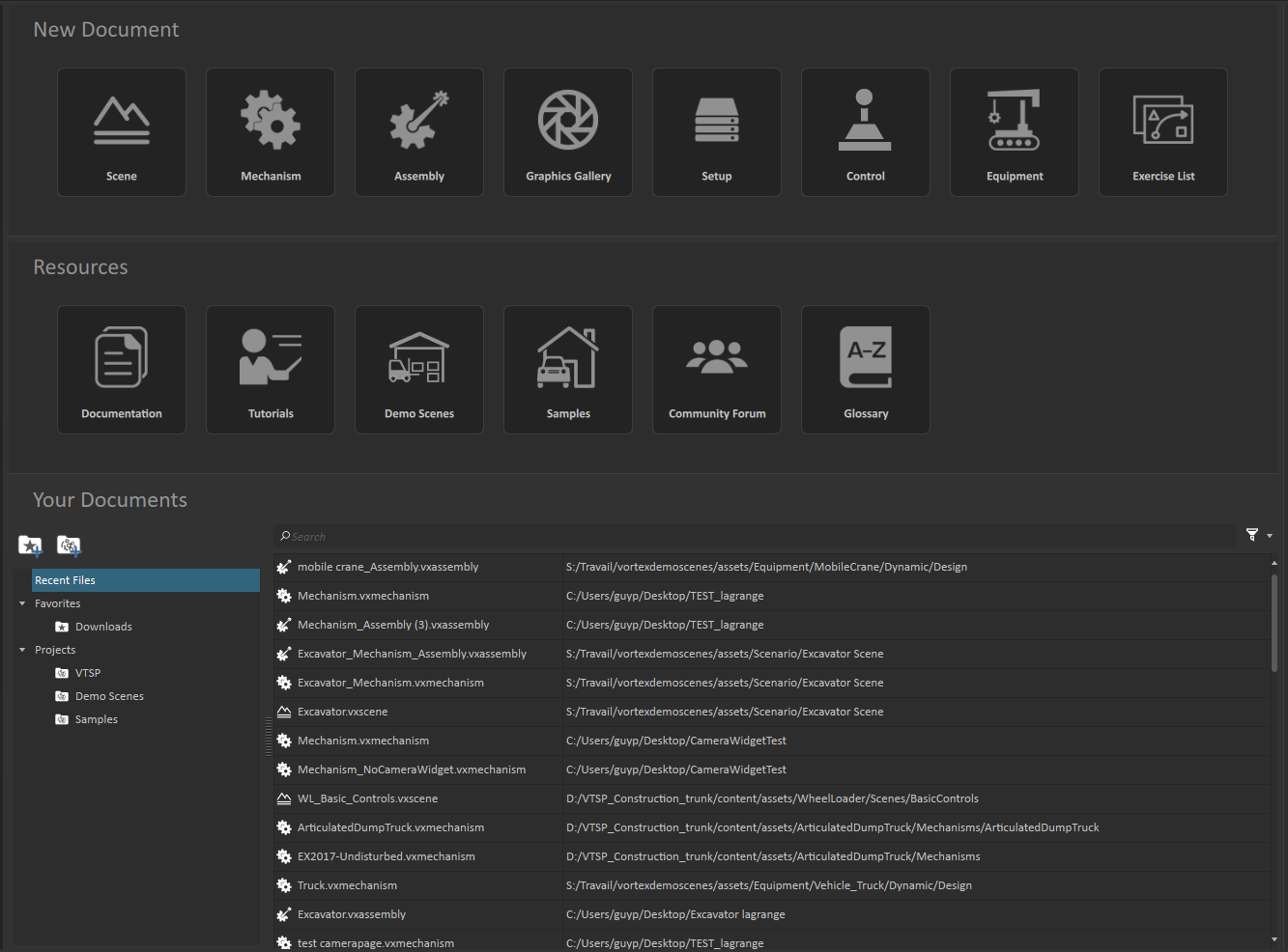
- Look at the file section. The center area is where you will find the interface as it relates to files.
- Near the top, there is a row of buttons to create a new document. Select the desired box to create that component.
- The middle portion contains quick links to Vortex Studio resources.
- The bottom portion shows the Asset Browser. It lists the recent files or the favorites and projects you defined. You can open any file by double-clicking on them. You can also filter what types of files appear in this list by clicking on the relevant icons.
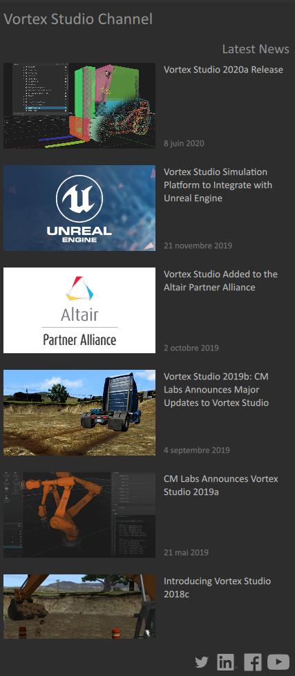
- Look at the Vortex Studio Channel. The right-hand side of the screen displays the Vortex Studio Channel, where you will find clickable links to all the latest Vortex Studio news, blog posts, and CM Labs social media pages.
The Interface of a Scene
Vortex Studio uses a hierarchy of file types to organize the content of a simulation, making it easy to re-use already existing objects.
A Scene contains Mechanisms, which are themselves composed of Assemblies, Parts, Collision Geometries, and Graphics Galleries. Simulator Setup files and Control Interfaces are file types used to configure the simulator and connect the control hardware, respectively.
Let's take a look at the interface of a scene.
- Open a scene. From the Home page, click Open and select the Engineering Parkour scene mentioned at the top of this page. You will notice that the window is divided into panels along the edges and the 3D View in the center. Let's take a look at some of the main ones.
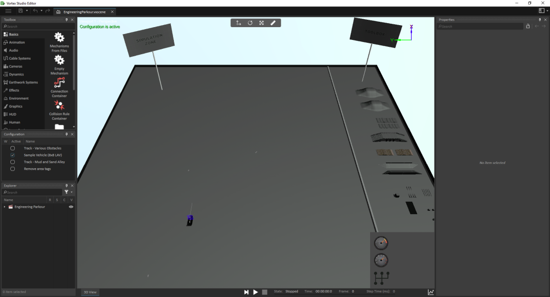
- Examine the panels. On the left and descending, there are:
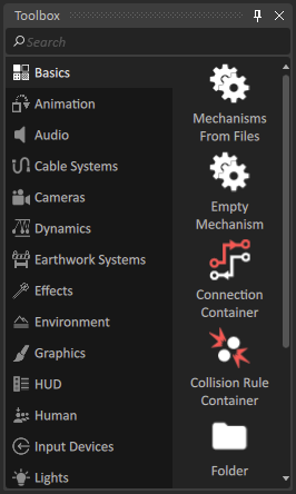
- The Toolbox, where you can add the different extensions to the simulation by double-clicking them or dragging them into the 3D view or Explorer panel.
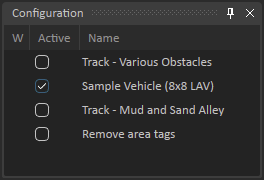
- The Configuration Panel, where you can customize and store a set of non-default values for objects to easily switch between different arrangements of elements in your simulation.
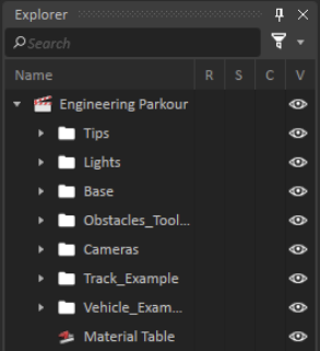
- The Explorer Panel, where you can view the entire hierarchy of your content. You can drag and drop elements here to change the order. Double-clicking an element of a different file type (e.g. double-clicking a mechanism found in a scene's Explorer panel) will open that element in a new tab for editing.
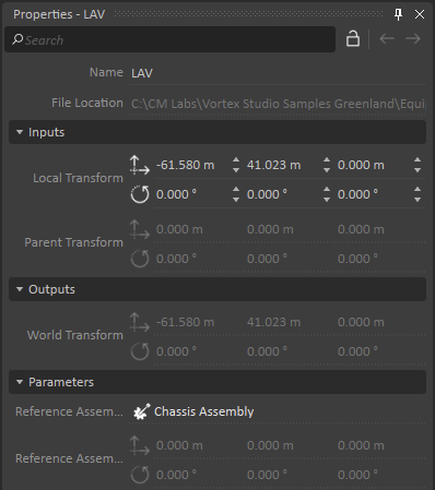
- On the right is the Properties Panel, where you view outputs and set inputs and controls once you click on an item from the Explorer panel.
Each panel has a pin icon and an x. The pin shrinks the panel to a tab along the side of the window to save space. Click on the tab and the contents of that panel reappear. Click the pin icon again and the panel reverts back to its open state.
The x icon closes a given panel. Panels can be reopened via the
 button found at the top right-hand corner of the screen.
You can also click the title bar of a panel and drag it to a new location.
- The Toolbox, where you can add the different extensions to the simulation by double-clicking them or dragging them into the 3D view or Explorer panel.
- Look at the top left of the screen. At the top left-hand corner of the screen, you will see (from left to right):
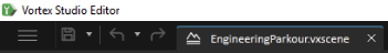
- The Home button: Returns you to the Home page discussed above.
- The Save button: Press this button to save your current file if there are any changes. Press the arrow next to the icon to reveal different saving options.
- The Undo and Redo buttons: Press the arrow next to the undo icon to see a history of actions you can undo.
- File tabs: Along the top, you will see a tab for each file you currently have open.
- Look at the 3D View. The 3D View displays the default viewport; it is the area where you can visualize your simulation. In the 3D view, you'll see:
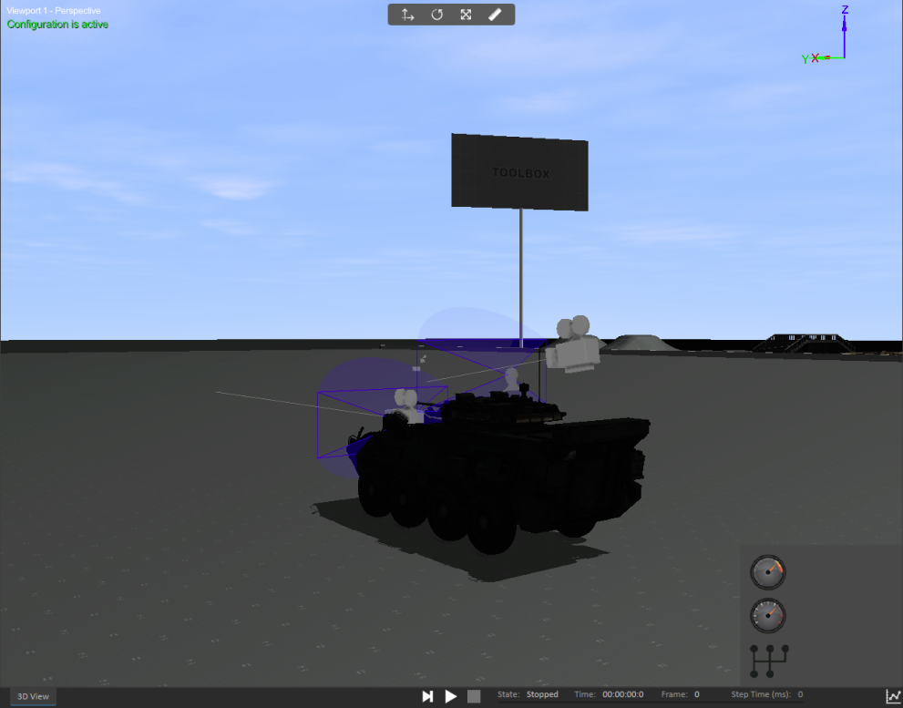
- A Transform toolbar at the top that allows you to manipulate objects directly in the 3D View.
- At the bottom, there are tools to run your simulation, like Play, Pause, and Stop buttons.
- A right-click menu where you can configure the display, change the grid options, and adjust the viewport configuration, among other functionality.
- Navigating the 3D View. Once you have content in your 3D View, you will naturally want to move around your simulation. This is mostly done with the mouse:
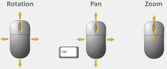
- Zoom: Scroll with the mouse wheel to zoom in and out from the center of the 3D View.
- Rotate: Click the middle mouse button and drag to rotate around the 3D View.
- Pan: To pan across the 3D view, hold Ctrl while also pressing the middle mouse button, then drag the mouse in any direction.
- Using the Plotter. The Plotter is a graphical interface that can display the data from the simulation to be used for debugging purposes, to look for behaviors that cannot be detected by the visual simulation. This data can then be exported to fine-tune the simulation and its parameters.
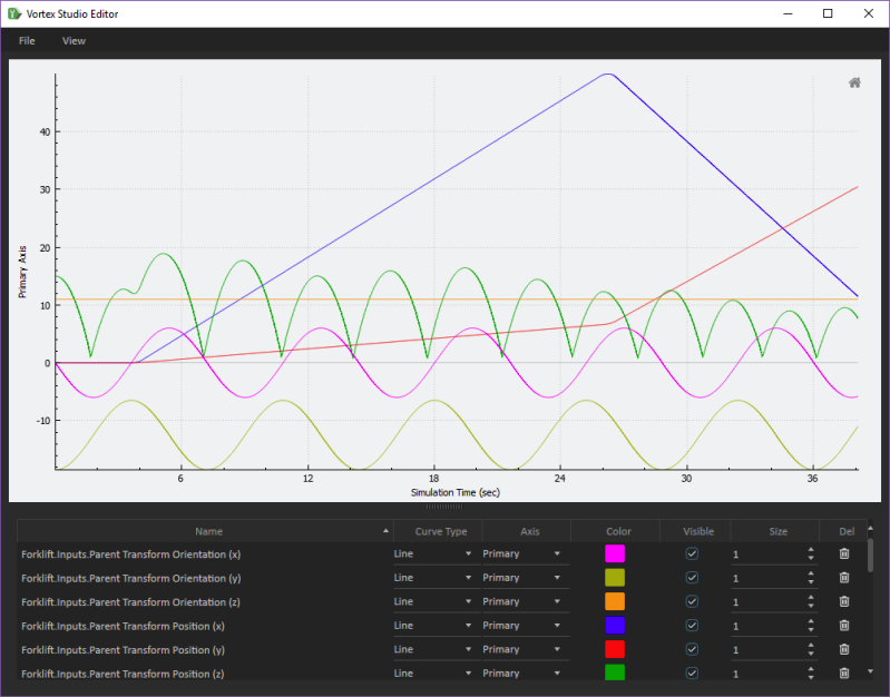
Access the Plotter by pressing the button found along the bottom right-hand corner of the 3D View.
Now that you have a basic understanding of the interface of a scene, you should feel comfortable to start exploring the Vortex Studio Editor. Next, we'll create a scene in the Editor to increase our familiarity with the Vortex Studio toolset.