Getting Started Tutorial 4 : Configuring a Mechanism
In this tutorial, you will take the mechanism created in Getting Started Tutorial 3 : Creating a Mechanism and give it life by motorizing parts, giving the mechanism interactive controls, and more. You will further enhance the simulation by connecting an input device and using a Python script to modify the functionality.
Prerequisites
You need to have Vortex® Studio and the Vortex Studio Demo Scenes installed to be able to follow all steps in this tutorial.
Additionally, a working knowledge of the Python coding language will be useful, but is not fully required. It is also commended to have an X-input gamepad connected to the computer.
Motorizing Constraints
In this step, we will assign motor properties to some of the constraints to make the forklift move.
- Double-click on the assembly to open it, if not already there.
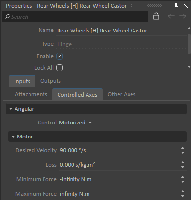
- Motorize the rear wheels by selecting the Rear Wheels [H] Rear Wheel Castor constraint. Select the Controlled Axes tab under the Input section of the Properties panel, then set the Control to Motorized using the drop down menu. Finally, set the Desired Velocity to 90 °/s.
- Next, motorize the steering. Select the Rear Wheel Castor [H] Body constraint. Select the Controlled Axes tab under the Input section of the Properties panel. Set Control to Motorized using the drop-down menu.
- Switch to the mechanism tab and test it to see that the forklift rolls forward.
Adding a Joystick Extension
In this step, we will add a joystick that we will use to control the forklift.
- Go back to the Forklift mechanism tab.
- Select Input Devices in the Toolbox and add a Joystick.
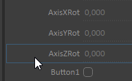
- Interact with the joystick hardware to see generated position data in the Properties panel.
Adding Connections
In this step, we will connect the joystick's outputs to the motorized constraints so that we can drive the forklift around.
- Add a connection container by selecting Basics from the Toolbox. Double-click Connection Container to add it to the Explorer panel. This will also open the Connection Editor, replacing the 3D View in the main window.
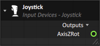
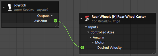
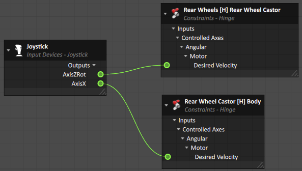
- In the Explorer panel, select the joystick extension. Then in its Properties panel, select AxisZRot and drag it into the Connection Editor in the main window.
- In the Explorer panel, select the Rear Wheels [H] Read Wheel Castor constraint. In its Properties panel, drag and drop Desired Velocity (found under the Motor sub-section of the Controlled Axes tab) to the connection container. Connect the AxisZRot output to the Desired Velocity input by dragging a line between the green circles of the output and the input.
- Create a second connection for steering between the AxisX property of the joystick and the Rear Wheel Castor [H] Body constraint's Desired Velocity.
- Switch to the 3D View tab of the mechanism and test it. Move the joystick axes to see the forklift drive. While the forklift moves, there is no way to modify the speed limits when the joystick is directly connected to the constraints; this requires scripting. Note that the lift graphics are not connected to any parts so they don't move.
Python Scripting
In this step, we will create a simple Python script to control the forklift. It will take input signals from the joystick extension, process them, and send out the result as outputs to the various constraints.
- Select Scripting from the Toolbox and add a Dynamics Script to the Explorer by double-clicking on it.
Right click Edit on the newly added script in the Explorer. In the resulting dialog panel, add inputs and outputs shown below using the Add buttons. When finished, click Ok.
Section Name Type Physical Dimension Inputs Steering Double None Inputs Throttle Double None Outputs Power Signal Double None Outputs Direction Signal Double None Control code often goes in pre_step or post_step. Make sure to get the spacing correct.
Pre_Step means the code is called at each step before the collision detection and the dynamic solver.
Post_Step means means the code is called at each step after the collision detection and the dynamic solver.
Read more about each function here.
Create a ForkliftController.py file with the code below. Using your preferred IDE, create a file named ForkliftController, and be sure to save it as a .py file.
In the Explorer panel, select the Dynamics Extension. In the Properties panel, select your ForkliftController.py Python file.
Proper spacing is critical for correct Python syntax. Never use a tab to indent.
Forklift Controller""" Called before the collision detection and before the dynamic solver. Use this method to get inputs or set values to dynamics objects. """ def pre_step(extension): steering = extension.inputs.Steering.value throttle = extension.inputs.Throttle.value extension.outputs.Power_Signal.value = throttle * 5 extension.outputs.Direction_Signal.value = steering * 2
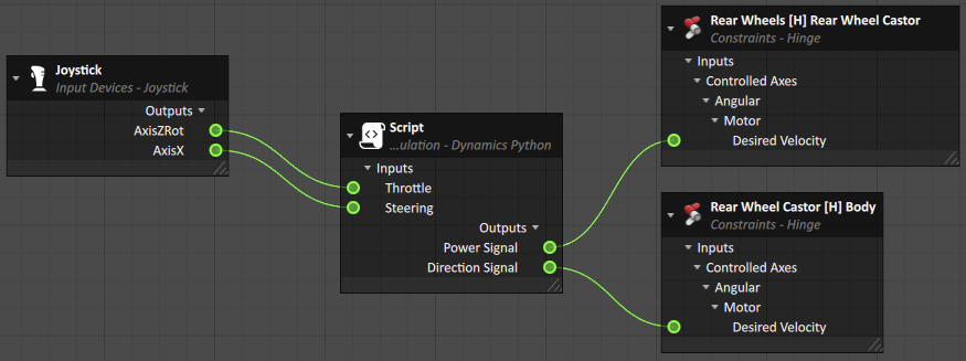
In the Connections, delete the existing connections by selecting them, then right-clicking and selecting Remove or pressing the Delete key. Create new connections between joystick, script and constraints (see table below).
Output Input Joystick > AxisX Script > Steering Joystick > AxisZRot Script > Throttle Script > Power Signal Rear Wheels [H] Rear Wheel Castor > Motor > Desired Velocity Script > Direction Signal Rear Wheel Castor [H] Body > Motor > Desired Velocity Make sure you use name the above inputs and outputs exactly as they appear in the table to match the code.
The connection container should look like the following:
Adding a Camera Extension
In this step, we will add a camera to get the viewpoint of the forklift driver.
- Switch back to the main window (the 3D View tab).
- Select Cameras in the Toolbox, and double-click Perspective to add it to the Explorer panel.
- Select the camera and reposition it to the driver's perspective using the Transform toolbar.
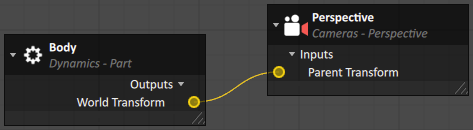
- Open the Connections from the Explorer panel. Create a new connection between the Parent Transform of the Camera's inputs and the World Transform of the Body part (found in the Outputs tab of its Properties panel). This will force the camera to follow the forklift body.
- Go back to the 3D View and right-click in the 3D View and select Viewport Configuration…. Choose a configuration with two viewpoints, then click Ok.
- Press the 'C' key to set the viewpoint to the camera in one of the viewports.
Add Basic Mast Controls
In this step, we will practice what we have learned so far to add some motion to the forklift's mast. We will also introduce the concept of limits, which set boundaries to the movement of a constraint.
- Under the Forklift Graphics Gallery, create new parts for the Mast and the Carriage (found under Mast > Mast 2nd Stage > Mast 3rd Stage).
- Double-click the assembly. In the Explorer panel, select Mast and Body by holding down the Ctrl key. Double-click Common Constraints > Hinge from the Toolbox (See table below for settings).
- Similarly, select Carriage and Mast in the Explorer panel. Double-click Select Common Constraints > Prismatic from the Toolbox (See table below for settings). Set both new constraints' Control field to Motorized under Controlled Axes in their respective Properties panels.
- In the Carriage [P] Mast constraint, in the Inputs > Controlled Axes tab, select the Limits box.
- Scroll down and set the following:
- Lower Limit > Position to 0 m.
- Upper Limit > Position to 1.8 m
- In Inputs > Controlled Axes > Linear > Motor, set the Desired Velocity to 1 m/s. Note that we are skipping the steps to create collision geometries and mass properties. In general, this should be done for every part.
Test the assembly to see the apron rise and stop.
Constraint Name Type Part 1 Part 2 Position Primary Axis (Part 1) Secondary Axis (Part 1) Mast [H] Body Hinge Mast Body 0 m; 0 m; 0 m +Y: 0 m; 1 m; 0 m +X: 1 m; 0 m; 0 m Carriage [P] Mast Prismatic Carriage Mast 0 m; 0 m; 0 m +Z: 0 m; 0 m; 1 m +Y: 0 m; 1 m; 0 m
To set the positions and axes of each constraint's Part 2:
- Click the "..." in the Offset (Relative) field of Part 2.
- In the resulting window, set the Copy From field to Attachment Offset: Part 1.
- Click Apply.
- Click Ok.
Add a VHL Interface
In this step, we will add a VHL interface that exposes some of the forklift's functions at the scene level. A VHL interface can be used to access the inputs, outputs and parameters from constraints, scripts and extensions.
- Open the mechanism file and go back to the mechanism window.
- Add a VHL Interface from the Simulation section of the Toolbox.
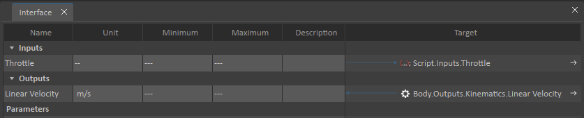
- In the Explorer panel, select Carriage [P] Mast constraint. In the Properties panel, select Controlled Axes > Motor > Desired Velocity and drag it to the Inputs section of the VHL Interface. Double-click on the newly created input name, and rename it to Mast Velocity.
- In the Explorer panel, select the Body part. In the Properties panel, select Output > Linear Velocity and drag it to the Outputs section of the VHL Interface.
- In the Explorer panel, click on Interface and test the mechanism and change the value of the Mast Velocity in the VHL interface to control it.