Creating a Vehicle from a Vehicle Preset
- DEVOPS
 Vortex® Studio provides a library of Vehicle Preset that are representative of different class of vehicles such as wheeled vehicle, rigid or flexible tracked vehicle along with a set of combination of different drivetrains
Note Before proceeding with any of the instructions in this section, you should have already imported a 3D model and built a chassis Part from it. Then you can follow the instructions for adding one of the powertrain presets to an existing vehicle mechanism. Once the powertrain is connected to the vehicle mechanism, you can adjust the preset parameters to customize how it behaves when simulating a vehicle.
The presets that are available offer a choice of heavy industrial equipment (trucks, excavator, etc.) and cars with choices for wheeled vehicles (all-wheel drive, front-wheel drive, etc.) or tracked vehicles:
| Preset Name | Transmission Type | Wheels | Tracks |
|---|---|---|---|
| Car AWD | automatic | 4 | -- |
| Car FWD | automatic | 4 | -- |
| Car FWD (Manual) | manual | 4 | -- |
| Car RWD | automatic | 4 | -- |
| Flexible Track Torque-Divider Transmission (Tank) | divider | -- | flexible |
| LAV 8X8 | automatic | 8 | -- |
| Packbot | automatic | -- | rigid |
| Skid Steering | automatic | 4 | -- |
| Hydrostatic Transmission Track (Excavator) | hydrostatic | -- | rigid |
| Track Torque-Divider Transmission (Bulldozer) | divider | -- | rigid |
| Trailer 2 Axles | -- | 4 | -- |
| Trailer 3 axles | -- | 6 | -- |
| Truck 2 axles | automatic | 4 | -- |
| Truck 3 axles | automatic | 6 | -- |
Creating a Vehicle
This procedure explains how to add a powertrain preset to an existing vehicle mechanism.
Open the mechanism where you have defined the vehicle.
Note If you do not have a mechanism file containing the vehicle parts, you can follow the instructions in Building Assemblies from a 3D Model and Building Parts from a 3D Model to import the 3D model that represents your vehicle and create parts for its chassis.
Select Vehicle Systems in the Toolbox. Double-click the desired vehicle preset.
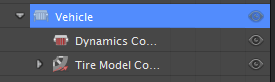
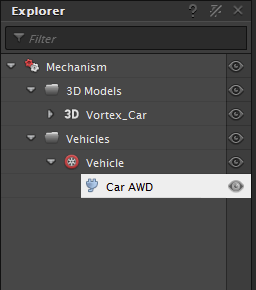
A new Vehicles folder appears in the Explorer panel with the preset you chose underneath it. Under the vehicle preset icon a number of new properties appear, which provide access to the parameters you need to customize your new vehicle.
Depending on the type of vehicle you are building, follow the instructions for one of these topics:
- For each wheel, see Connecting Wheels.
- For capturing the interaction between the wheels of a vehicle and the ground surface material, see Adding Tire Models.
- For each track, see Connecting Tracks.
To customize the engine, brakes, steering, etc., see Configuring the Vehicle's Dynamics.
Connecting Wheels
These steps describe how to associate the graphics representation of the wheel to the Vehicle Systems power-train and position them properly in the vehicle.
In the Explorer panel, click the Connection Editor folder to open the Connection Editor. If there is no Connection Container create one via the Toolbox.
From the Explorer panel, click the vehicle preset, for example Car AWD.
The properties now appear in the Properties Panel.
In the Properties panel, under the Outputs section, expand the Front Left Wheel parameter.
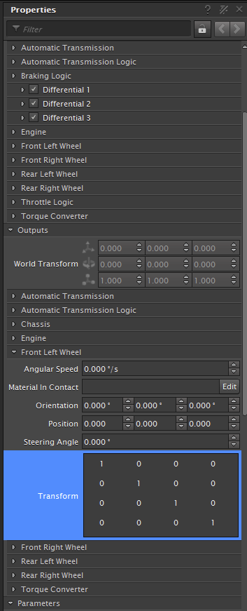
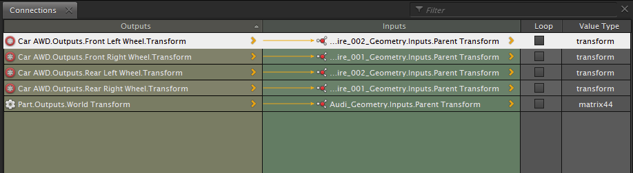
Click and drag the Transform parameter into the Output header of the Connections folder.
Repeat step 3 for the Front Right Wheel, Rear Left Wheel, and the Rear Right Wheel.
You will now connect the graphics to the vehicle presets.
In the Explorer panel, in the 3D models folder click the Left Wheel graphic node.
In the Properties panel, in the Inputs header, click and drag the Parent Transform to the Input header in the Connection Editor to the line with the Corresponding wheel vehicle preset.
Repeat steps 6 and 7 for each wheel.
The graphic wheels are now connected to vehicle presets.
If in the 3D view the wheels are not positioned correctly, see Adjusting Moved Wheels to modify the wheel positions.
Adjusting Moved Wheels
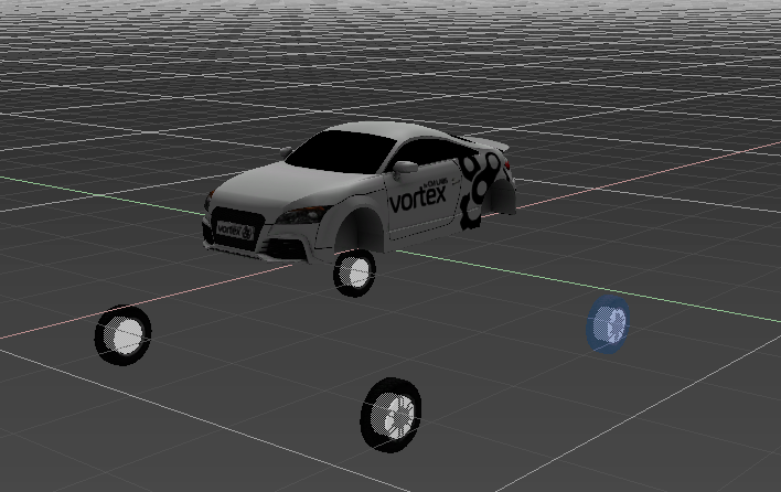
In some cases after you have connected wheels to your vehicle preset, you may notice the wheel graphic now appears in a different location than it should.
This procedure walks you though how to use the position of the wheel's graphic asset to adjust the position of the wheel part created by the vehicle preset.
From the Explorer panel, right-click on the Vehicle Preset, for example Car AWD and click Properties from the context menu.
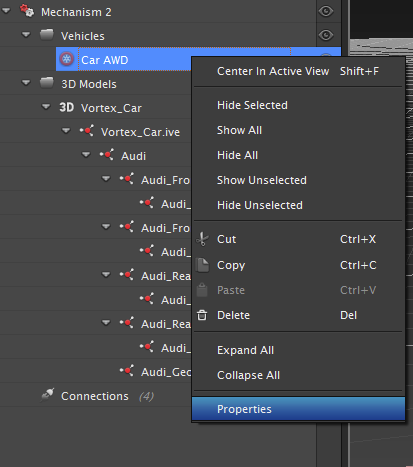
The Car AWD properties appear in a pop-up window.
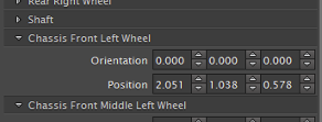
Scroll down towards the bottom of the property page until you see a Chassis ... Wheel section (for example, Chassis Front Left Wheel).
From the Explorer panel, click on the graphic asset node that matches the wheel you want to adjust.
Its position and orientation values appear in the Property Panel.
Use the Local Transform position values of the graphic asset node as a guide for the Chassis ... Wheel values,.
For example, in the picture below the graphic asset for the left front wheel appears in the Command Panel while the Chassis Front Left Wheel is being edited. The values to enter for the Position parameter are
1.187,0.786,0.346.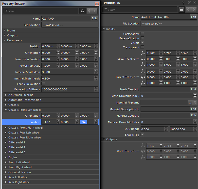
When you are finished, the 3D asset for the wheel appears again in the correct place.
Repeat these steps for every wheel you need to adjust.
Connecting Tracks Steps
Although there are many properties common to all tracks (regardless of whether they are rigid or flexible) in Vortex, rigid tracks are represented by a fixed graphic asset, whereas flexible tracks are generated at runtime.
For this reason, rigid tracks do not have to be manually connected to graphical nodes like flexible tracks.