Working with Tire Models in Vehicle from Preset
- DEVOPS
Having at end a vehicle that has been created from a Vehicle Preset or from a Modular Vehicle Systems, there are few differences in working with it.
Using the Tire Models
When creating a new vehicle system, the Tire Model component is also created. The set of wheels is already set up but the set of Tire Types is empty; the user has to create the tire types (e.g., front wheels, rear wheels).
For each tire type, you must define a set of tire model properties. Right-click on a tire type and choose one of the available tire models. Next, set the Ground Material field to one of the materials proposed by the drop-down menu (or add another entry, if desired). For a given tire type, all ground materials must be different, otherwise a warning message appears.
At the end of this process, each tire type should have a tire model property defined for each possible collision geometry's material that may eventually collide with the wheels in the scene.
Before running the simulation, check for warning messages.
Important:
- When using the Tire Models, the usual material table is not used to define the interaction between the wheels and other collision geometries of the scene. Instead, it's the "interaction table" defined in Tire Type Collection that is used. This table persists in the mechanism file.
- The material assigned to a Vehicle System's wheel component is ignored.
The data set under the Tire Type Collection in the Explorer panel corresponds to the material table. In the usual material table, the first row and the first column represent the material and the entry of the table defines the classical contact interaction. In the Tire Type Collection, the tire type corresponds to the first column and each ground material corresponds to the top row. Each entry in the table becomes the tire model interaction.
Note Combinations of tire type and ground material that are not defined use the Default Tire Model that is found under the Tire Model Component in the Explorer panel.
Structure of the Tire Model Extension
Main Components
The Tire Model Extension is the main entry point to the Tire Model feature. Newly created vehicles from presets come automatically equipped with a Tire Model Extension (which you can delete to revert to the material table if desired).
The Tire Model extension is structured as a tree of sub-extensions under the vehicle in the Explorer panel, the first level of which contains the following sections:
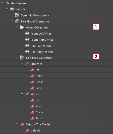
- Wheel Collection: contains a set of wheel adapters, one per wheel of the given vehicle.
- Tire Type Collection: contains a user-defined set of tire types and their tire model properties.
- Default Tire Model: contains the user-defined tire model property that is used during simulation when no tire model has been defined for a specific tire type/ground type interaction. By default, the Coulomb Tire model is selected, but it can be replaced by the user.
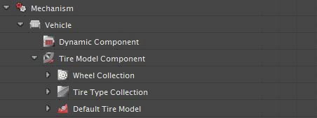
Expanding the Tire Model Component reveals:
- The set of wheels contained in the current vehicle
- The Tire Type Collection. In this example, the collection contains two user-defined tire types: Summer and Winter. Each collection contains a set of four user-defined Tire Models that will be used for specific tire type/ground type interactions during simulation.
First key point in setting up the Tire Model Component of a vehicle is to associate a Tire Type with every wheels of the vehicle. Having defined a set of tire models under a tire type, the second key point is to associate each of them to a ground material. In general, these materials are already assigned to the terrain database. When the wheel travels on some ground surface, the simulation system identifies the type of tire associated with this wheel and the material associated with the ground at the contact patch, and applies the appropriate ground reaction forces according to the given tire model. As such, for each pair of interacting tire type/ground material, the user can define a tire/ground interaction model which should be used to add the necessary reaction forces to the wheel.
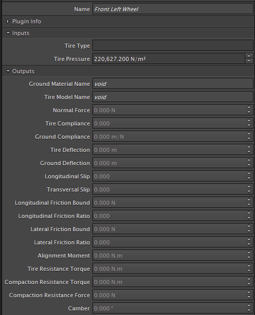
The Wheel Adapter
The wheel adapter is used to assign specific tire type/ground type interactions to a given wheel in the vehicle. For this purpose, it lets the user select a tire type and gives control over the tire pressure of the wheel. Finally, it provides a selection of useful simulation outputs.
Selecting a wheel from the wheel collection opens up its Properties panel.
|
|
Tire Model Properties
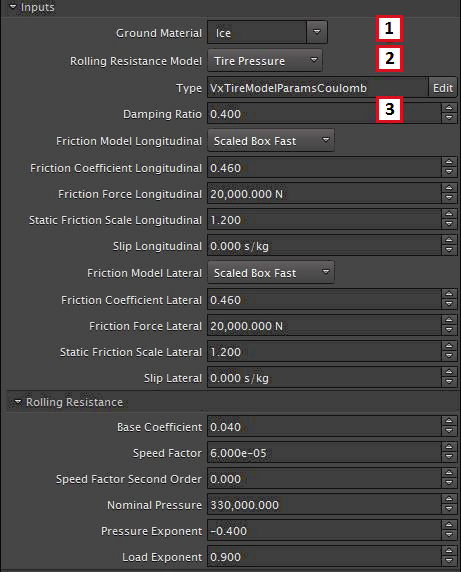
Each tire type can have any number of tire models defined for it. Right-clicking the type (e.g., Summer) reveals a menu that give access to tire model properties. Selecting a model (e.g., Ice) open its Properties panel.
A tire model defines the way a wheel reacts to the ground taking into consideration ground penetration, traction, side force, and resistance to movement. All tire models introduced in here are further explained in the Tire Models section of the Technical Notes.
There are a few inputs common to all models. The following uses the Coulomb Tire Model as an example.
- Ground Material: The name of the Material assigned to the ground.
- Rolling Resistance Model: Sets the rolling resistance model.
- Damping Ratio: The damping scale factor on the critical damping as computed automatically based on the stiffness at the contact. Stiffness at the contact is computed based on the tire pressure and the width of the tire.
Note, more information about the inputs shown above are found in the Tire Models section of the Technical Notes.