Fluid Interaction Technical Notes
- DEVOPS
Vortex® supports the real-time simulation of dynamic rigid bodies immersed in fluid, and simulates different effects due to fluid interaction, such as buoyancy, drag, lift, and added mass. The fluid simulation capabilities offered by Vortex do not provide the same level of physical realism as complex Computational Fluid Dynamics (CFD) methods but are sufficient for use in real-time, immersive simulation environments, e.g., in the context of virtual training simulators.
The buoyancy, drag and lift effects are modeled as external forces which are applied to the rigid bodies. These forces are calculated according to the shape of an object, its immersed parts in the fluid, and the velocity of the fluid relative to the object's surface. Vortex offers fluid interaction with many different shapes including primitives (boxes, spheres, capsules, cylinders), as well as mesh types (VxConvexMesh, VxTriangleMeshUVGrid, VxTriangleMeshBVTree).
Added mass is a purely inertial property. An added-mass matrix modifies the rigid body inertia; it is not simulated by adding forces as for the other phenomena. Added mass acts on the acceleration of a body, before external forces are applied.
For each volume of rigid body, the immersed volume and the relative velocity on each submerged surface are calculated to generate the resultant fluid forces. For convex and general mesh volumes, computations are done for each triangle. Consequently, when more triangles are used to define the shape, the simulation is more accurate.
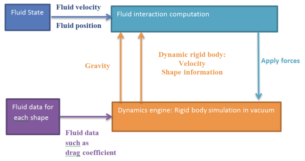
Fluid State
Various fluid dynamics forces are computed and added to a part based on the overlap of the part's collision geometries with a volume of fluid, called a fluid state.
A fluid in Vortex is represented by Vx::VxFluidState, the interface between the Vortex fluid interaction algorithms and the fluid itself. The fluid state provides access to the fluid's properties, such as the fluid surface height at any point, the density and the velocity.
Several geometry types can be used to represent a fluid in Vortex:
- Planes (see Vx::VxPlanarFluidState)
- Heightfields (see Vx::VxHeightFieldFluidState)
- Triangle meshes (see Vx::VxTerrainFluidState)
You can add one or more fluids to your simulation. A part overlapping with a fluid will be subject to the hydrodynamic forces explained in the following sections.
Best Practices for Fluid Interactions
The following list provides guidance to producing accurate fluid interactions:
- For best accuracy in the computation of fluid effects on a body, a triangle mesh should be used to represent the shape of the body.
- Primitive shapes (spheres, capsules, cylinders, boxes) are computationally less demanding but will also give less accurate results than meshes in the computation of buoyancy, drag or lift forces.
- If a mesh is used to represent the shape of a body, a reasonable fine triangulation of the mesh should be used with close to equilateral triangles for best results.
- Fine tuning of the mesh resolution may be required to balance computational efficiency and accuracy of the fluid interaction.
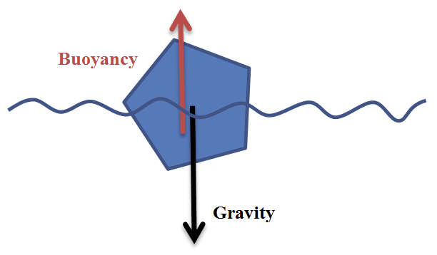
Buoyancy Force
Buoyancy is an upward force opposed to the weight of a object immersed in fluid. The buoyancy force, B, acts on the center of the submerged volume according to the following formula:
![]()
where:
- ρ is the fluid density
- b is the buoyancy scale computed from the displaced volume
- V is the volume of the immersed part of the object collision geometry
- g is the gravity force
Note The buoyancy scale is a factor used in Vortex® to fine-tune the buoyancy force. It can be used to compensate for volumetric information which is not captured by the collision geometry (e.g., holes in the structure).
Consequently, if the rigid body is above the fluid surface, no forces are generated; if it is below, the buoyancy force is determined using the entire volume of the object (VCG) computed using the volume of its associated collision geometry. Otherwise, the exact submerged volume of the rigid body is computed to achieve an accurate simulation.
You can set Vx::VxCollisionGeometry::FluidInteractionData::setBuoyancyCenter if the buoyancy force is intended to act on a position other than the default position. This position can also be set in the Editor.
In the Vortex Studio Editor, you must set the displaced volume. The relationship between the displaced volume VDISP, the buoyancy scale b and the collision geometry volume VCG is given by the following equation:
![]()
For information about setting the buoyancy in the Editor, see Enabling Buoyancy.
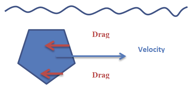
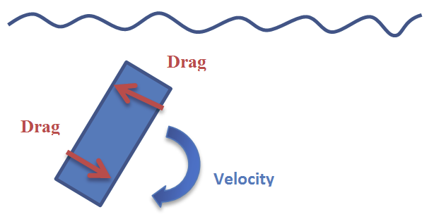
Drag Force
Drag is a force opposite to the relative velocity of a moving object inside a fluid.
The drag force, D, is applied to the middle of the exposed surface on all types of surfaces for all collision geometries, according to the following formula:
![]()
where:
- d is the drag coefficient provided by the user
- ρ is the fluid density
- v is the object's velocity relative to the fluid
- A is the cross-sectional area perpendicular to the relative velocity
Note The drag coefficient is not necessarily the same in each direction. For this reason, the user can specify a different drag coefficient value along each local axis of the collision geometry, which is specified as a three dimensional vector. For example, a box shape can have three different drag coefficients along its X-, Y-, and Z-axes. For a sphere, only the X-component of the vector is used as the uniform drag coefficient in all directions. However, for a cylinder and capsule, the drag coefficient for the faces (cylinder) or caps (capsule) is given by the Z-component, while the drag coefficient for the body is given by the X-component only.
In Vortex®, drag is set up for a collision geometry by modifying the drag coefficients along the respective translation and rotation axes of the volume. The drag force is applied considering the linear and the angular velocities of the geometry and the linear fluid flow velocity. The latter can be specified in the fluid state. If a mesh is used to represent the body's shape in the interaction with the fluid, the body's surface is discretized into small surface patches and the contributions to the total drag force of every patch are computed and integrated.
It is recommended to use a fine triangular mesh (ideally with equilateral triangles) to represent rigid bodies. If you need to change the value of the drag coefficient, you can set it in the Editor or Vx::VxCollisionGeometry::FluidInteractionData::setDragCoefficient.
For information about how to set the drag force in the Editor, see Enabling the Drag Force.
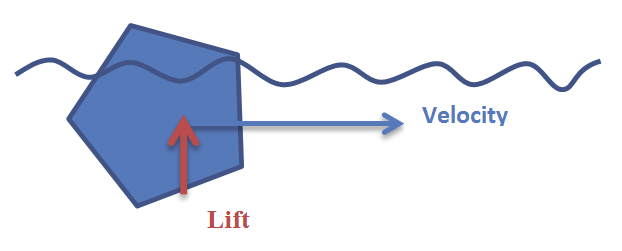
Lift Force
The lift is a force orthogonal to the object velocity and is applied to the middle of the surface. The lift force is described by the following formula:
![]()
where:
- l is the lift coefficient provided by the user
- ρ is the fluid density
- v is the object velocity
- n is the surface normal
- A is the cross-sectional area perpendicular to the relative velocity
Note The lift coefficient is not necessarily the same in each direction. For this reason, the user can specify a different lift coefficient value along each local axis of the collision geometry, which is specified as a three dimensional vector. For example, a box shape can have three different lift coefficients along its X-, Y-, and Z-axes. For a sphere, only the X-component of the vector is used as the uniform lift coefficient in all directions. However, for a cylinder and capsule, the lift coefficient for the faces (cylinder) or caps (capsule) is given by the Z-component, while the lift coefficient for the body is given by the X-component only.
If the normal surface of the collision geometry is collinear or perpendicular to the relative object velocity, there is no lift applied on this surface. Also, there is no lift if objects are symmetric about the direction of movement.
The force depends on fluid density, projected area along the path, velocity, and angle of attack. The lift coefficient is a dimensionless value that depends on the desired angle of attack, Mach number, and Reynolds number. In Vortex®, lift force is set for a geometry by modifying the lift translation coefficients along its respective axes.
It is recommended to use a fine triangular mesh (ideally with equilateral triangles) to represent rigid bodies. You can set the coefficient in the Editor or via Vx::VxCollisionGeometry::FluidInteractionData::setLiftCoefficient.
For information about how to enable lift in the Editor, see Enabling the Lift Force.
Added Mass
Added mass (also known as virtual mass) is an effect resisting the acceleration of a dynamic rigid body inside a fluid. When a body changes its velocity, it also moves some volume of the fluid that surrounds it. Due to the surrounding fluid, the acceleration of the body is affected, and will be slower. Afterward, the fluid around the rigid body accelerates and moves according to the rigid body motion. Then, when the rigid body tends to slow down, the velocity of the surrounding fluid makes the deceleration slower.
The added mass can be considered as a force related to the object's acceleration relative to the surrounding fluid. Simulating the added mass by applying forces tends to be a source of instability, unless high simulation frequencies or higher order integrators are used (which is usually not the case in an interactive simulation setting). The body acceleration has an effect on the forces generated by the added mass, and the forces applied on the body have a direct effect on its acceleration. For this reason we use a different approach to simulate the added mass: the tensor K. It is represented by a 6x6 matrix. The tensor is the sum of the mass-inertia tensor KB and the added mass tensor KF:
![]()
where:
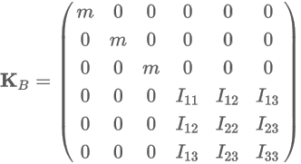
and:
- Iij are the components of the inertia tensor
- m is the mass
The added mass tensor KF can be used to simulate a dynamic rigid body in a fluid, and has the following form:
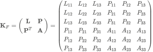
The sub-matrix L represents the coupling between linear motions, the sub-matrix A couples angular motion, and the sub-matrix P couples the angular motion with the linear motion. Note that KF is symmetrical, as are L and A, but not P.
Note The added-mass tensor KF has to be provided by the user. The user must know how to compute this tensor to simulate the effect of the added mass. See Configuring the Added Mass.
The physics pipeline in Vortex® is capable of managing the full 6x6 mass matrix K (defined above) in the equation of motion. The mass matrix is used to compute the acceleration from forces, and to solve the various constraints. Due to the inclusion of KF in K, the fluid effects upon the rigid body are accounted for in the simulation.