Inertia Tensors
- DEVOPS
This section lists inertia tensor types as well as advanced topics on inertia tensors in the Vortex® world.
Spherical Inertia Tensor
An inertia tensor with three equal moments of inertia on the diagonal and zero off-diagonal values is known as spherical, suggesting that the mass is distributed evenly in every direction. This case is typified by objects whose mass distribution has spherical symmetry, however this is not a necessary condition. For example, regular polyhedra such as cubes and tetrahedra also have spherical inertias. Even irregular asymmetric objects can happen to have mass distributions that result in spherical inertia. The following matrix gives the inertia tensor of a sphere of uniform density with radius r: \(\)
Cylindrical Inertia Tensor
Two equal moments of inertia on the diagonal indicate that the inertia has a single rotational symmetry about the remaining axis. In Vortex this is achieved with a cylinder primitive. Generally, this case is typified by spheroids, that is, ellipsoids with two equal principal axis lengths. Depending on the relative length compared to the remaining principal axis, the spheroid can be characterized as either an oblate or prolate spheroid.
The following matrix gives the inertia tensor of a cylinder of uniform density, aligned along the z axis with radius r, and height h:
\(\)
Note Be careful with the ratio of the radius and the height or length, as long thin objects generate high velocities and impulses at the extremities, which could lead to unstable simulations.
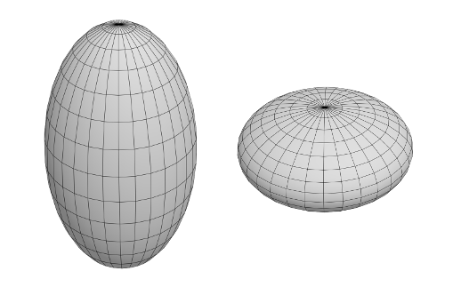
Prolate and Oblate spheroids
Cuboid Inertia Tensor
There are three distinct moment of inertia values on the diagonal. In Vortex this is achieved with a cuboid primitive geometry. This case is typified by an ellipsoid where all three principal axis lengths are different. The following matrix gives the inertia tensor of a cube of uniform density with x,y,z dimensions given by width w, height h, and depth d:
\(\)
Properties of Inertia Tensors
The inertia tensor is represented as a 3 x 3 matrix (nine components) as shown here:
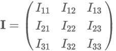
- The values on the main diagonal are independent and known as "moment of inertia" values.
- The values on the off diagonal are known as "product of inertia" values.
The three values on the diagonal from top-left to bottom-right are independent, and the following values in the matrix are equal:
- I12 = I21
- I13 = I31
- I23 = I32
Note In the Vortex Studio Editor Properties panel, you can manipulate these values directly in the inertia tensor table, which is also presented as a 3 x 3 matrix. This matrix with values reflected across the main diagonal, as shown above, is known as symmetric. The inertia tensor is "positive-definite" because it has the property that for any unit vector u, the moment of inertia about u, given by the product uTIu has to be positive. In Vortex, the inertia tensor does not have to match the 3D graphics file as the distribution of mass in an object is usually not uniform in density. Some insight comes from considering the inertia tensor of an object about a point as the sum of the inertia tensors of its constituent point mass particles due to their offset positions from that point. The inertia tensor of a point mass m, offsets from the origin by a vector p as given by the formula shown here:
where E is the 3x3 identity matrix.
Therefore, writing the components of the position offset vector p as (x y z)T the matrix on any axis is expanded as shown here:
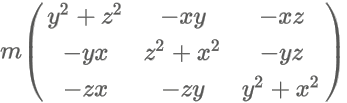
The matrix is zero when the position offset is zero. If the particle lies about that, then the moment of inertia about the two remaining axes is equal to the off-diagonal products of inertia.
Ranking Inertia Tensors for Simulation Efficiency
The following table indicates the rank, from best to worst, of the inertia tensors that you can use for simulation stability and efficiency:
| Rank | Inertia Tensor | Notes |
|---|---|---|
| 1 | Spherical | Use this option by default, except where differences between length and width or height are important. |
| 2 | Cylindrical | Use this option where one edge is longer. This is useful for objects such as ground obstacles, such as logs, in vehicle simulations. It also gives a reasonable approximation of humans on the ground. |
| 3 | Cuboid | Use this option sparingly. It is commonly used when the object's mass is distributed differently in length, width, and height. |
Note The middle axis will always be unstable and subject to chaotic motions. Arbitrary cuboids allow axes with axis ratios beyond 10:1. Length dimension ratios of 10:1 lead to moment of inertia ratios of 100:1. Thus, 100:1 leads to moment of inertia ratios of 1000:1. Using unbalanced numbers risks instabilities during simulation, and therefore objects need to be carefully parametrized. If more than one object with large ratios is used during simulation, the problem is compounded during collisions at runtime. The general rule of thumb is to avoid or limit complexity during simulation. Thus, use the simplest mass properties that meet the requirements of fidelity. For example, avoid large mass ratios of large ratios of moment of inertia.
Linear and Rotational Inertia
In the same manner that linear inertia (or mass) is used in force and momentum calculations, the inertia tensor is used to find torque and angular momentums.
The following table compares linear and rotational calculations:
| Linear Inertia | Rotational Inertia Equivalent |
| Mass = m | Inertia tensor = I |
| Velocity = v | Angular velocity = w |
| Linear momentum = p = m*v | Angular momentum = L = lw |
| Acceleration = a | Angular acceleration = \({\alpha}\) |
| Force = ma | Torque = \(I{\alpha}\) |
Inertia tensors for most typical geometries have been calculated. In simulation, it is recommended to use a simplified inertia tensor. Spheres and boxes create stable simulations, while parts that are long and thin, or asymmetric may be unstable when simulated.