Earthwork Tools
- DEVOPS
Learn about specialized tools to help simulate most types of earthmoving equipment and operations.
A number of specialized tools are available to help simulate most types of earthmoving equipment and operations.
- The Bucket tool represents the bucket appendage on an excavator-type vehicle. It can dig up soil from an Earthwork Zone or from a soil bin, carry it to another zone or soil bin, and then pour it out.
- The Blade tool represents the blade on the front of a bulldozer-type vehicle. It cannot pick up soil, but can displace it (push it) to an adjacent portion of an Earthwork Zone or a Soil Bin.
- The Generic Bucket tool represents the wide bucket appendage on wheel loaders and other types of earthmovers. It is similar in function to the bucket tool, but its shape can be customized to match the real thing.
Note In some cases, it may be useful to disable the ability of the above tools to deform soil. For a bucket, select the Dynamics Bucket in the Explorer panel. In the resulting Properties panel, deselect the checkbox located next to "Inputs".For a blade, select the Dynamics Blade in the Explorer panel. In the resulting Properties panel, deselect the checkbox located next to "Inputs".For a generic bucket, select Generic Bucket > Bucket Face in the Explorer panel. In the resulting Properties panel, deselect the checkbox located next to "Inputs". It is not recommended to toggle this option while the tool is in contact with a soil surface.
Bucket
A bucket is a type of Earthwork deformation tool that is set up in a mechanism. It is a box-like structure used to scoop up soil, e.g., the bucket of an earthmoving excavator.

Before adding a bucket to a mechanism, the latter should first be created with all the relevant parts, constraints and logic.

To add a Bucket extension:
- In your mechanism, select Earthwork Systems in the Toolbox.
- Double-click Bucket to add one to your mechanism, or drag it into the 3D View.
A bucket icon appears under the mechanism in the Explorer panel. This extension contains the physical parameters of the bucket.
The next step is attaching the bucket to the corresponding part and graphics node of the mechanism. Once they are properly attached to the mechanism, we will configure the four Bucket Tool extensions in order to ensure that their related properties use the correct position, orientation, shape and size values when calculating contact, or rendering soil materials.
Attaching the Bucket to a Part
- From the Explorer panel, click the bucket. The bucket properties appear in the Properties panel.
- Under the Parameters section near the bottom, click the Browse button in the Part field, then
 .
. - From the Explorer Panel of your mechanism, go into the Assembly, then locate and click on the Part that you've set up for the bucket of the mechanism.
- The part's name appears in the Select Part dialog box. Click the Confirm button.
The bucket part's name now appears in the parameter box and the bucket accessory position is now relative to the bucket part's origin.
Configuring the Bucket Extension
After connecting the bucket part and node to the Bucket extension, the accessories are now clustered around the bucket's origin. We need to modify the values so the bucket will be positioned correctly.
- From the Explorer panel, click the bucket. The bucket properties appear in the Properties panel.
- Ignore the Inputs and Outputs sections and go directly to the Parameters section.

- Configure the fields below.
- Material: Type the name of the material you want to use for the bucket in the Material text box (e.g., a bucket material was created for the Excavator demo scene).
- Part: This is the part for the bucket that was attached in the previous step.
Shape Model: Modify the values in the Shape Model parameters of the bucket until it takes on the dimensions, position and orientation of the bucket's 3D model.
The values must be changed in the Shape Model parameter boxes. The manipulators (Move/Rotate/Resize) cannot be used to change these values.
Blade
The blade tool is a generic, user-customizable surface that can push soil around. It can be used to model most types of dozer blades.

Unlike the bucket, which has a very specific shape, the Blade tool gives you complete control over the shape of the deformation tool, so you could design any number of flat or angled blades with which a vehicle might use to push soil around or build a trench.
Note A ripper cannot be accurately represented with the Blade extension, because it is thin and induces a significant outward soil flow during cutting. The cutting force of the blade is computed with a model which is applicable only to wide blades with a high width-to-depth ratio, or cutting tools with side walls which prevent any lateral soil flow.
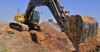
Before adding a Blade extension to a mechanism, the latter should be first created with all the relevant parts, constraints and logic. You will need to define the collision geometries that determine the shape of the blade; for example, if creating a standard bulldozer blade, you might define five box shapes, two for the side walls, one for the bottom, and two for the largest part of the blade. The excavator blade shown below has four box collision geometries, with no side walls. When creating the CGs, it is a good practice to give them clear names.

To add a Blade extension:
- In your mechanism, select Earthwork Systems in the Toolbox.
- Double-click Blade to add one to your mechanism, or drag it into the 3D View.
A new extension with a blade icon appears under the mechanism in the Explorer panel, with no accessory shown in the 3D Viewport (yet). It contains the physical parameters of the blade.
Configuring the Blade Extension
The next step is to connect the blade part and the collision geometries to the Blade extension, specify the material to use, and disable collisions on the collision geometries.

From the Explorer panel, click the Blade extension. The Blade properties appear in the Properties panel.
- Material: Type the name of the contact material you want to use for the blade in the Material text box (for example, the Bucket material was used for the Excavator demo scene).
- Part: This is the reference Part for the blade.
Click the Browse, then. From the Explorer panel of your mechanism, go into the assembly, then locate and click on the part that you have set up for the blade of the mechanism. The part's name appears in the Select Part dialog box. Click the Confirm button. The blade part's name now appears in the parameter box. Template CGs: This section has two parameters, size and collision geometry fields. Size specifies the number of collision geometries you want to use (this can be changed later if need be).
For each collision geometry field, click the Browse button, then in the numbered reference box. The Select (Number) dialog box appears. From the Explorer panel of your mechanism, go into the assembly, locate the part that you have set up for the blade, then click on its collision geometry. The name of the collision geometry appears in the numbered reference box. Click the Confirm button, and repeat the operation for the next collision geometry field.
While selecting the various collision geometries in the Blade extension, they will be highlighted in blue on the blade part.Make sure that collision detection is disabled for each collision geometry by following these steps:Open the Part file where the collision geometry is defined.Click on the icon for that collision geometry in the Explorer panel to load its properties page in the Properties panel.Under the Collision Detection section, clear any check mark in the Enabled option.The CGs serve as templates only and will be cloned by the Earthwork Systems module in order to produce an identical set of CGs which provide digging capability. Disabling the original template CGs is therefore important to enable the tool to penetrate the ground. If they were not disabled, the standard rigid collision response associated with the original CGs would prevent any penetration with the soil.
Generic Bucket
This is a customizable version of the basic bucket. Its shape can be modified to simulate a dragline bucket, or a wheel loader's front bucket, for example.

Before adding a Generic Bucket extension to a mechanism, the latter should first be created with all the relevant parts, constraints and logic. Also, the geometric shape of the bucket should be modeled with a set of collision geometries. We recommend the use of primitive geometries only, such as cylinders for the side walls and boxes to model the general curved shape of the bucket's interior.
To add a Generic Bucket extension:
- In your mechanism, select Earthwork Systems in the Toolbox.
- Double-click Generic Bucket to add one to your mechanism, or drag it into the 3D View.
A new Generic Bucket folder appears under the mechanism in the Explorer panel. After creation, the generic bucket already contains a single bucket face. Bucket faces define the side walls of the bucket and are configured analogously to the blade. This extension is used to model the geometric shape of a single face/side of the bucket with which the tool can dig. For example, a wheel loader bucket would require at least three bucket faces: two for the side walls, and one for the curved interior shape and the teeth of the bucket.

By right-clicking on the Generic Bucket folder, it is possible to add more bucket faces:
- Add Bucket Face: Adds another bucket face to the generic bucket, which is modeled by a Blade extension. See above for configuration of the Blade extension.
Multiple bucket faces are required for pretty much any bucket design (for example, a wheel loader bucket would need three bucket faces at least). It is also used when the bucket is composed of multiple moving parts, but this is a specialized case. In order to measure the payload in the bucket, you can add a Soil Mass Sensor to the generic bucket from the Toolbox. The payload information can be useful for the collection of operator performance metrics.
The right-click menu also offers two additional, though optional features for visualization of the soil in the bucket. For best visual representation of soil, the SSM feature described in the Soil Particles Extension topic should be used instead.
- Add Soil Surface: Adds a Soil Surface folder which contains two extensions, Graphics Soil and Soil Mass Sensor. This is to visualize the soil particles contained in the bucket by wrapping them with a height field mesh.
- Add Particle Effect: Adds a Particle Effect folder which contains two extensions, Particle Spray and Plane Sensor. This is to emit additional visual particles when the dynamics soil particles are being poured out of the bucket.
Note You can also add the Generic Bucket extension to a configuration from the right-click menu.
Configuring the Soil Surface
 Configuring the Graphics Soil Extension
The Graphics Soil extension visualizes the particles accumulating in the bucket by lifting a height field mesh along its local up-axis. So it is ideal to tilt it such that the local up-axis (indicated by the arrow of the accessory) points into the general direction along which the particles accumulate inside the bucket (e.g., against gravity if the bucket is in the upright position).
Note that the bounding box of the Graphics Soil extension has to be placed inside the bucket and not overlapping with the side walls of the bucket. The bounding box defines the region in which the Graphics Soil extension will sample the surface of the bucket and place the height field mesh which will later be erect to cover the particles accumulating inside. Therefore it should overlap only with the bottom of the bucket and not with its side walls to avoid any visual glitches during simulation.
From the Explorer panel, click Generic Bucket > Soil Surface > Graphics Soil. The Graphics Soil properties appear in the Properties panel.
The editable properties are:
- Visible: If checked, the soil particles appear in the 3D viewport.
- Cast Shadow: If checked, the soil particles will cast shadows (this is computation intensive).
- Receive Shadow: If checked, the soil particles will receive shadows cast by other objects.
- Graphics Material: This points to a graphics material within a gallery, that determine the general appearance of the soil particles (texture, reflectivity, etc.).
NoteTo allow flexibility at runtime, you can expose this parameter via a VHL so that the operator can select the correct graphics material for the specific scenario. See Working with VHL Interfaces.
- Local Transform: Modify these values to position the Graphics Soil accessory.
- Parent Transform: These values can be connected via a connection container to the World Transform output of a bucket's part. The accessory will then follow that part.
- Dimensions: Modify these values to resize the Graphics Soil accessory to match the 3D model's dimensions.
- HeightField
- Cell Size X, Cell Size Y: This is set automatically, based on the Number Vertices field.
- Num Vertices X, Num Vertices Y: These values define the resolution of the height field mesh in the local X and Y direction. For tools which are rather square, such as an earthmoving excavator bucket, the same number of vertices should be chosen in both directions. For rectangular, non-square tools, e.g., a wheel loader bucket, a higher vertex count should be chosen in the direction of largest extent.
- Parameters
- Terrain Upscaling: Modifies the upscaling between the input and output zones when displacing soil.
- Particle Spreading: The particles which are travelling on the surface of the dynamics height field, and which are transferred to the Graphics extension from the Dynamics extension, are wrapped by the Graphics height field. The Particle Spreading parameter defines how much the volume of a single particle will be spread out on the graphics height field's surface. Setting this to the value X will affect all height field cells which are touching the circle with radius "X * particleRadius", placed at the center of the particle. Also refer to Inflation Factor below.
- Blend Range: This value (in meters) determines the interval (starting from the Blend Bias) over which displaced soil is blended.
- Blend Bias: This value (in meters) determines the height at which a mound of displaced soil is visible to the user.
- Blend Enable: Selecting this box activates soil blending.
- Blur Enable: Selecting this box activates blurring when soil is in motion.
- Minimum Height Deformation: Minimum height deformation relative to the original soil surface to apply the Graphics Material on the deformed area, in meters. This parameter is used only in subtract mode.
- Lowering Factor: This value help to reduce graphical artifacts when the height field mesh matches the original mesh. The Lowering Factor determines the height offset to apply to the height field mesh, in meters.
- Terrain Nodes: This node has to be set to the graphics node that represents the geometry of the container. The Graphics Soil extension will sample the shape of the container and ensure that the visualized soil will appear correctly. Increase the size field to add more nodes.
- ShowParticles: This parameter is a debugging flag that allows visualizing the particles which are received by the graphics soil extension. These particles will be used in the "particle wrapping stage" which lifts the graphics height field in order to wrap the soil particles which travel on the surface of the dynamics height field. The particle wrapping feature can be used to mimic homogeneous material types such as sand. Indicates whether the particles are shown, for debug purposes. All the particles attached to the soil are shown.
- Inflation Factor: Defines how much of the particle volume should be considered for the wrapping effect. It is used in the "Particle wrapping stage" in which the graphics height field is lifted off in order to wrap soil particles which travel on the surface of the dynamics height field. Setting the inflation factor to 1.0 will lift the height field as high as needed to account for 100% of the volume of the soil particles. A value of 0 will turn the wrapping feature off.
- Blend Mask: Specifies a black and white texture file used to determine the initial dug state of the soil. White portions of the texture file indicate an area where the material initially appears as dug, while black areas appear untouched.
- Update Rate: This field is used to reduce the amount of CPU cycles used for rendering graphics by setting an amount of time to wait between each update (in seconds). For instance, if the update rate field is set to 1.0, the graphics will be updated once every second.
Configuring the Soil Mass Sensor Extension
The Soil Mass Sensor extension serves two purposes:
- It calculates the mass of the soil particles currently in the bucket and hence can be used to obtain the current payload.
- It gathers all the soil particles in an output list (Particles) which gets communicated to the Graphics Soil extension. The latter uses the provided information to wrap the soil particles in the bucket with a visual height field mesh for a smoother look of the soil in the bucket.
From the Explorer panel, click Generic Bucket > Soil Surface > Soil Mass Sensor. The Soil Mass Sensor properties appear in the Properties panel.
- Local Transform: Modify these values to position the Soil Mass Sensor accessory within the bucket. It is important to position the soil mass sensor such that it contains the entire bucket. It can stick out of the bucket if that is needed to fully cover the entire bucket range.
Also, make sure that when the bucket is completely filled and soil particles pile up high inside the bucket, these particles will be inside the region defined by the soil mass sensor. Otherwise, some of the payload in the bucket will not be considered in the output mass calculations of the soil mass sensor - Parent Transform: These values can be connected via a connection container to the World Transform output of a bucket's part. The accessory will then follow that part.
- Dimensions: Modify these values to resize the Soil Mass Sensor accessory to match the 3D model's interior dimensions.
- Particle Mass Only: If this box is selected, the soil mass sensor only calculates the mass from soil particles but not from soil grids (zones, soil bins) overlapping the sensor. This is checked on by default in the Generic Bucket as it greatly reduces the computation time spent in the calculation of the output mass while the bucket is digging inside a zone.
- Particles: This output drives the Graphic Soil extension. It is set automatically. The Mass output shows the mass of soil currently in the sensor. It can be used in a script or displayed in a HUD.
Configuring the Particle Effect
Configuring the Particle Spray Extension
Typically, the Particle Spray should be positioned on the edge of the bucket where the particles leave the bucket during a pouring operation, e.g., at the teeth of an excavator bucket. The size of the particle spray defines the region in which the particles get spawned at random locations and is defined by the Emission Box properties described below.
From the Explorer panel, click Generic Bucket > Particle Effect > Particle Spray. The Particle Spray properties appear in the Properties panel.

- Local Transform: Modify these values to position the Particle Spray where you would expect the fine soil dust to appear as they are dropping off the bucket. This is typically near the teeth of the bucket.
- Parent Transform: These values can be connected via a connection container to the World Transform output of a bucket's part. The accessory will then follow that part.
- Visible: If selected, the soil particles appear in the 3D viewport.
- Cast Shadow: If selected, the soil particles will cast shadows (this is computation intensive)
- Receive Shadow: If checked, the soil particles will receive shadows cast by other objects.
- Graphics Material: Points to a graphics material within a Graphics Gallery, that determines the general appearance of the fine soil dust (texture, reflectivity, etc.).
- Particle Lifetime: Determines how long the dust particles will exist after their creation (in seconds).
- Particle Size Range: Determines the range of possible sizes of the dust particles, in meters. The Z-component is ignored.
- Particle Alpha Range: Determines the range of possible transparency of the dust particles. The Z-component is ignored.
- Particle Alpha Fade Interval: Determines how many seconds will pass between the particles fading in and out.
- Particle Color Start: Determines the starting color of the particles. The four color fields represent red, green, blue and opacity.
- Particle Color End: Determines the ending color of the particles. The four color fields represent red, green, blue and opacity.
- Particle Color Change: Sets a variance in brightness for the particles within the start and end colors selected above. For each particle, a random amount from -255 to 255 multiplied by this value is added to each color component.
- Particle Angle Start Range: Determines the range of angles at which the particles can be oriented at their creation. The Z-component is ignored.
- Emission Rate: Determines how many particles are emitted when an impact event is received (in hertz).
- Emission Enabled: Determines when particles are emitted. It is controlled by the Dynamics Plane Sensor.
- Emission Box Minimum: Determines the minimum dimensions of the box from which particles emit (in meters).
- Emission Box Maximum: Determines the maximum dimensions of the box from which particles emit (in meters).
- Spray Cone Theta Range: Determines the range of angles from the +X-axis that the spray cone can take (in degrees). The Z-component is ignored.
- Spray Cone Phi Range: Determines the range of angles from the +Z-axis that the spray cone can take (in degrees). The Z-component is ignored.
- Spray Linear Speed Range: Determines the range of linear speeds the particles can travel (in meters per second). The Z-component is ignored.
- Spray Angular Speed Range: Determines the range of angular speeds the particles can rotate (in degrees per second). The Z-component is ignored.
- Gravity Acceleration: This value changes the effect of gravity on the particles (in meters per second squared).
- Particle Limit: Sets a maximum number of particles to be used in the dust clouds.
Configuring the Plane Sensor Extension
The soil particles which are leaving the bucket (e.g., during pouring of soil), will cross the dynamics plane sensor. When this happens, the Particle Spray will emit visual particles to create the illusion of additional fine soil material which is poured out of the bucket. The Particle Spray and Plane Sensor extensions are connected in order to achieve this.
The Plane Sensor accessory should be positioned in a way that optimizes detecting when dynamic soil particles are poured out. Therefore, it should be perpendicular to the teeth of the bucket part (or close to it) in order to best detect falling particles. Ensure that its Z-axis points into the bucket.
Note When testing out the plane sensor, keep in mind that the visual particles (emitted by the Particle Spray) may appear close to the teeth even when the dynamic particles cross the sensor far away from them because the Particle Spray is positioned close to the bucket teeth. You should experiment with the size and position of the Plane Sensor in order to achieve the optimal effect.
From the Explorer panel, click Generic Bucket > Particle Effect > Plane Sensor. The Plane Sensor properties appear in the Properties panel.

- Local Transform: Modify these values to position the Sensor accessory until it is perpendicular to the teeth of the bucket part.
- Parent Transform: These values can be connected via a connection container to the World Transform output of a bucket's part. The accessory will then follow that part.
- Number of Particles: Number of particles which are crossing the sensor in the current frame. They are communicated to the Particle Spray extension to trigger emission of visual particles. This value is set automatically.
- Dimensions: Modify these values to resize the Plane Sensor accessory to match the 3D model's dimensions