Earthwork Zone
- DEVOPS
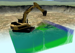
Learn how to define where the terrain can be deformed or piled with soil.
Earthwork Zones are used to define where the terrain can be deformed or piled with soil. They are defined using a bounding box that intersects with the scene's terrain. They are inserted under the File Terrain in the Editor.
Earthwork Zones can be diggable (meaning that soil can be removed and the terrain can be deformed) or non-diggable (meaning that soil can only be piled up in the zone and no topographic changes can be made).

Adding an Earthwork Zone
Because Earthwork Zones are defined on a terrain, you must first set up a terrain before trying to define the Earthwork Zone in the Scene Editor. See Terrain for more information. Once this is done, add an Earthwork Zone.
To add an Earthwork Zone:
- In your scene, select Earthwork Systems in the Toolbox.
- Double-click Earthwork Zone to add one to your scene.
Two new additions appear in the Explorer panel (Earthwork Zone, Earthwork Systems), and a red box is set in the 3D View to indicate the location and dimensions of the zone. The Earthwork Zone will be found under the terrain object.
When adding an Earthwork Zone for the first time, you can add the following extensions. (These are placed in the Scene under a top-level folder named "Earthwork Systems".)
- Soil Materials: Specifies a soil type from a list of presets (e.g. sand or loam), and sets up global simulation limits on the number of particles. Also, removal of stationary particles can be configured. Please refer to the section Choosing a Soil Type for more information.
- Soil Particles: Used to visualize the simulated soil particles.
- Soil Dust: Used for simulation and visualization of dust created during earthmoving operations, e.g., digging and dumping.
Note When it is first created, warnings appear in the Soil Particles extension because geometries have not been assigned yet for the rock particles. This is normal.
Choosing a Soil Type
The Earthwork Systems use presets to define the various characteristics of the soil. There are four presets available: Loam, Sand, Clay, and Gravel.
You may configure your scene with one specific soil type. It is not currently possible to have mixed soil types within a scene (both gravel and sand, for example).
The preset is selected within the Soil Materials extension, which can be found within the Earthwork Systems folder. For more information, refer to Configuring the Soil Material.
Moving/Rotating/Resizing the Earthwork Zone
You can choose to resize, reposition, or rotate the zone using either of these methods (in the screenshot, the zone's size has already been increased from the default):
- By using the Transform tools in the 3D View.
- By editing the values directly in the Parameters section of the Properties panel.
Note that the Dynamics component of the Earthwork Zone should be selected in order to perform the above tasks.

Configuring the Dynamics Properties of an Earthwork Zone
Click the Dynamics extension under Earthwork Zone in the Explorer panel. The Properties panel now displays the Dynamics properties for the Earthwork Zone.

- Local Transform: Modify these values to position the Earthwork Zone (communicated visually via the red box accessory in the 3D Viewport).
- Parent Transform: Receives transform from the Earthwork Zone. It is set automatically.
- Shear Strength: Scales the shear strength of the soil in an Earthwork Zone, affecting its resistance to shear forces. Reducing this value will make the soil slip more easily, hence reducing the angle of repose. Also, less force will be needed to cut through the soil.
Lowering the shear strength to 0% will cause the entire soil to immediately start spreading out and only come to rest once it reaches a flat state. This can be done at runtime and is useful in certain earthmoving training scenarios.
Setting the shear strength to any value between 0% and 100% will scale the stable slope angles of the soil between the maximum angle of repose possible for that soil type and completely flat, as shown in the following figure.
Runtime modification of the shear strength can be useful for soil stability tuning or for the simulation of mud-like material (even poured concrete can be mimicked with this feature). It can also be used at runtime to prepare a soil pile dynamically for an upcoming digging operation. For example, in a bulk material handling simulation, the shear strength can be drastically reduced in order to make bulk material in a cargo hold spread out as a preparation for a clamshell grab moving the cargo ship-to-shore. In reality, this task is performed by heavy machines such as wheel loaders or bulldozers. In a simulation context, in-depth modeling of the wheel loaders' operation could be considered too complex or irrelevant, in which case the dynamic shear strength modification can be used instead to provide the same end result. - Flow Velocity Scale: A value between 0 and 100% that determines how quickly the soil in this zone flows.
- World Transform, Dimensions, HeightField, Particles: These outputs are used to drive the graphic extensions. They are set automatically.
- Mass: This output shows the total mass of soil in the zone. It can be used for scripts or to be displayed in a HUD.
- Parameters:
- Diggable: By default, digging cannot occur below the original terrain surface; only dumping material is possible. However, digging below the terrain's surface can be turned on by selecting the Diggable box.
- Visual Imprints: Indicates whether dynamically controlled parts can leave a visual imprint on the zone. This imprint is only a visual effect and does not affect the physics simulation. See Visual Imprint. This field only appears when Diggable is selected.
- Initial Relative Density: This field only appears when Diggable is selected.
The relative density defines the amount of void space contained in the soil, or, in other words, how loose or compact the soil is. A relative density of 100% indicates that the soil is at its maximum compaction level while 0% indicates the loosest state for the soil. This is a relative quantity, since the actual amount of void space contained inside a given soil depends on the chosen soil type.
The Initial Relative Density parameter sets the relative density in which the simulated soil will be initially when the simulation starts. At runtime, the relative density of the soil can change locally depending on the occurrence of simulated events such as digging, dumping or induced soil slip. The accessory of the Earthwork Zone provides a way to visualize the relative density of the soil at any point in the simulation. It can be enabled by right-clicking the eye icon beside the Dynamics component of the Earthwork Zone, as indicated in the following screenshot:
- Material: This is the material used for contacts with the soil. Refer to the Materials Table section.
- Dimensions: Modify these values to resize the Earthwork Zone accessory (you can also use the Resize manipulator in the 3D View), in meters.
- Cell Size: The height field of the terrain is divided into square cells, each cell representing the top of a virtual column that rises or lowers as soil is added or removed. You can modify the default Cell Size parameter to improve the accuracy of the soil simulation; the smaller the cells, the more columns there are and the more precise the soil displacement.
The preferred ratio of tool width to cell size is about 10 or more. In other words, a tool that is one meter wide would require a cell size of about 0.1 meters for best results. Making the cells smaller than this improves the accuracy but requires more computing power. - Output Mass: If selected, the mass contained in this zone is computed and provided in the Mass output field.
- Output Particles: If selected, the Particles output will be filled, which allows it to be transferred to the Graphics extension in the Earthwork Zone and which ultimately allows the Graphics extension to wrap the particles with the visual height field.
In the Graphics extension, the Inflation Factor configures how much the graphics height field should be lifted off due to particles traveling on the dynamics height field.
Configuring the Graphic Properties for the Earthwork Zone
Click the Graphics extension under Earthwork Zone in the Explorer panel. The Property panel now displays the Graphics properties for the Earthwork Zone.
By default, disturbed soil appears white. In order to customize its appearance, customize the graphics material fields.

The following fields can be found in the Inputs and Parameters sections of the Properties panel.
- Visible: If selected, the displaced soil appears in the 3D viewport.
- Cast Shadow: If selected, the displaced soil casts shadows (this is computation intensive).
- Receive Shadow: If selected, the displaced soil receives shadows cast by other objects.
- Graphics Material: This points to a graphics material within a Graphics Gallery that determines the general appearance of the disturbed soil (texture, reflectivity, etc.).
- Local Transform: Modifying these values will change the position of the Earthwork Zone visuals. For most use cases, they should not be modified, as it will offset the graphics relative to the dynamics, which is generally undesired.
- Parent Transform: Receives transform from the Dynamics extension. It is set automatically.
- Initial HeightField: This sub-section is used to provide the extension with the initial height values and material of the terrain into which we can dig. This is usually provided through the capture extension which is positioned right over the height field extension (same position and size).
- Parameters
- Terrain Upscaling: Used to create a higher level of visual detail without having to increase the number of Dynamics cells, which can otherwise be computationally costly.

- Particle Spreading: The particles which are traveling on the surface of the dynamics height field, and which are transferred to the Graphics extension from the Dynamics extension, are wrapped by the graphics height field. The Particle Spreading parameter defines how much the volume of a single particle will be spread out on the graphics height field surface. Setting this to the value X will affect all height field cells which are touching the circle with radius "X * particleRadius", placed at the center of the particle. Also refer to Inflation Factor below.
- Blend Range: This value (in meters) determines the interval (starting from the Blend Bias) over which displaced soil is blended.
- Blend Bias: This value (in meters) determines the height at which a mound of displaced soil is visible to the user. In the image below, the soil extends down into the truck, but due to the Blend Bias, the bottom portion is invisible (highlighted by the longer red line). The Blend Range (highlighted by the shorter red line) blends the specified portion of the soil, starting at the Blend Bias point.

- Blend Enable: Selecting this box activates soil blending
- Blur Enable: Selecting this box activates blurring when soil is in motion.
- Minimum Height Deformation: Minimum height deformation relative to the original soil surface to apply the Graphics Material on the deformed area, in meters. This parameter is used only in subtract mode.
Lowering Factor and Rising Factor: Sometimes, when using highly detailed terrain files, artefacts may appear around the edges of a height field. In order to hide their appearance, you can alter the Lowering Factor and Rising Factor parameters to create a height offset. This units of these fields are in meters.


Lowering Factor Rising Factor - CellOverlapNumber: This field specifies the number of cells of the height field that overlap with the surrounding terrain. This is useful for hiding gaps between the height field and the terrain.

- Terrain Nodes
- Size: Increase the value of this field to add terrain nodes; this is needed in the case where the related Graphics Gallery has more than one node at the root level. Note that when modifying the related Graphics Gallery, the terrain nodes get reset to a single graphics node found at the root level. In this case, setting the terrain node must be redone.
In the resulting rows, use the Browse buttons to select graphics nodes of the capture mesh used to fill the heights of the height field. - ShowParticles: This parameter is a debugging flag which allows visualizing the particles which are received by the graphics soil extension. These particles will be used in the "particle wrapping stage" which lifts the graphics height field in order to wrap the soil particles which travel on the surface of the dynamics height field. The particle wrapping feature can be used to mimic homogeneous material types such as sand.
- Material Capture: If this box is selected, the texture of the original terrain (specified by the terrain nodes specified above) will be sampled and used as the initial texture of the graphics soil height field.
- Inflation Factor: This parameter defines how much of the particle volume should be considered for the wrapping effect. It is used in the "Particle wrapping stage" in which the graphics height field is lifted off in order to wrap soil particles which travel on the surface of the dynamics height field. Setting the inflation factor to 1.0 will lift the height field as high as needed to account for 100% of the volume of the soil particles. A value of 0 will turn the wrapping feature off.
Blend Mask: Specifies a black and white texture file used to determine the initial dug state of the soil. White portions of the texture file indicate an area where the material initially appears as dug, while black areas appear untouched.


Blend Mask Texture Applied Blend Mask - Update Rate (sec): This field is used to reduce the amount of CPU cycles used for rendering graphics by setting an amount of time to wait between each update (in seconds). For instance, if the update rate field is set to 1.0, the graphics will be updated once every second.
- Size: Increase the value of this field to add terrain nodes; this is needed in the case where the related Graphics Gallery has more than one node at the root level. Note that when modifying the related Graphics Gallery, the terrain nodes get reset to a single graphics node found at the root level. In this case, setting the terrain node must be redone.
- Terrain Upscaling: Used to create a higher level of visual detail without having to increase the number of Dynamics cells, which can otherwise be computationally costly.
Child Extensions
Expanding the Graphics extension in the Explorer panel exposes additional details about the extension. The settings of the child extensions are determined based on the settings of the height field, and are mostly locked.
Once you add a Graphics extension, the following child extensions appear under it in the Explorer panel:
Graphics Connections
Double-click this to view the graphics connections. In very specific cases, to manipulate certain locked Graphics extension fields, you will need to sever the required connections.
Graphics Capture
Selecting this child extension reveals information related to capturing the materials of the terrain. The following fields are not locked and are available for you to manipulate.
- Visible: If checked, the soil particles appear in the 3D viewport.
- Local Transform: Determines the position of the capture.
- Trigger Capture: Selecting this box triggers a sampling of the terrain to be used as the initial texture of the graphics soil height field.
- Texture Width, Texture Height: These parameters define the X and Y resolutions of the texture which are used as a target in the material capture stage (see parameter Material Capture). In that stage, the texture of the original terrain surface is sampled and written into a texture that is then used for the initial appearance of the graphics soil height field at simulation start (before any deformations have occurred through tools or soil layers).
- Color Buffer Override: Selects a texture to override that specified in Captured Color Buffer.
- Normal Buffer Override: Selects a texture to override that specified in Captured Normal Buffer.
- Specular Buffer Override: Selects a texture to override that specified in Captured Specular Buffer.
- Shininess/Occlusion Buffer Override: Selects a texture to override that specified in Captured Shininess/Occlusion Buffer.
- Depth Buffer Override: Selects a texture to override that specified in Captured Depth Buffer.
Graphics Hole
Selecting this child extension reveals information related to the hole in your terrain. You can change its position by manipulating its Local Transform but the other inputs are locked.
Adding a Soil Mass Sensor
The soil mass sensor can be used to calculate the mass of the soil overlapping a specified region of interest. The region of interest is represented by an oriented bounding box.
You can add a soil mass sensor to help detect when certain conditions appear (for example, when there are no longer any soil particles within the sensor bounding box) or simply to measure the amount of soil in a location. For example, a soil mass sensor can be used to designate a trench which should be dug out as part of a training scenario. Once there is no more mass inside the trench, the scenario could be considered as completed.

To add a Soil Mass Sensor:
- In your scene or mechanism, select Earthwork Systems in the Toolbox.
- Double-click Soil Mass Sensor to add one, or drag it into the 3D View.
The Soil Mass Sensor extension checks the mass of the soil inside its volume (represented in the 3D viewport by a box accessory).

From the Explorer panel, click the Soil Mass Sensor entry under Earthwork Zone to open its Properties panel.

- Local Transform: Modify these values to position the Soil Mass Sensor accessory.
- Parent Transform: Use this if the Soil Mass Sensor needs to follow the transform of another object.
- Dimensions: Modify these values to resize the Soil Mass Sensor accessory to the desired dimensions (in meters).
- Particle Mass Only: If selected, the output mass of the soil mass sensor will be exclusively calculated from soil particles which are present in the sensor's region of interest. Any soil in height fields (Earthwork Zone and soil bin) will be ignored in the computation.
- World Transform: This output provides the current world transformation of the soil mass sensor.
- Particles: Mass: These are particles which are in the bounds of the soil mass sensor. When adding a "Soil Surface" to a Generic Bucket, this output is used to transfer the particles contained by the bucket to the Graphics Soil extension associated with the soil mass sensor.
The Mass field shows the mass of soil currently within the volume of the sensor. It can be used in a script or displayed in a HUD.NoteThis value includes mass of any soil in the region of the sensor (both soil in Earthwork Zone and soil bins, and soil in the form of soil particles).
Visual Imprint
The Visual Imprint feature allows soft soil to appear deformed when it interacts with a dynamically controlled part in an Earthwork Zone, for example, a heavy box landing on the ground, or a vehicle moving across terrain leaving ruts. This imprint is a visual effect only and does not affect the physical simulation.
To activate Visual Imprint:
- Select the Dynamics component of the Earthwork Zone in the Explorer panel.
- In the resulting Properties panel, select Visual Imprints.
- Select the Graphics component of the Earthwork Zone in the Explorer panel.
- In the resulting Properties panel, in the Parameters section, enter a value for Minimum Height Deformation. If any object colliding with the ground depresses it more than this parameter, the deformed texture appears.
Note The deformed soil material is specified by the Graphics Material input field, found by selecting the Graphics component in the Explorer panel.
The depth of penetration an object produces on the ground depends on its weight and the contact material stiffness. The higher the weight and/or the lower the stiffness, the higher the deformation will be.